

selecting capacitors with regards to ripple
 Mike W
Posts: 105
Mike W
Posts: 105
·
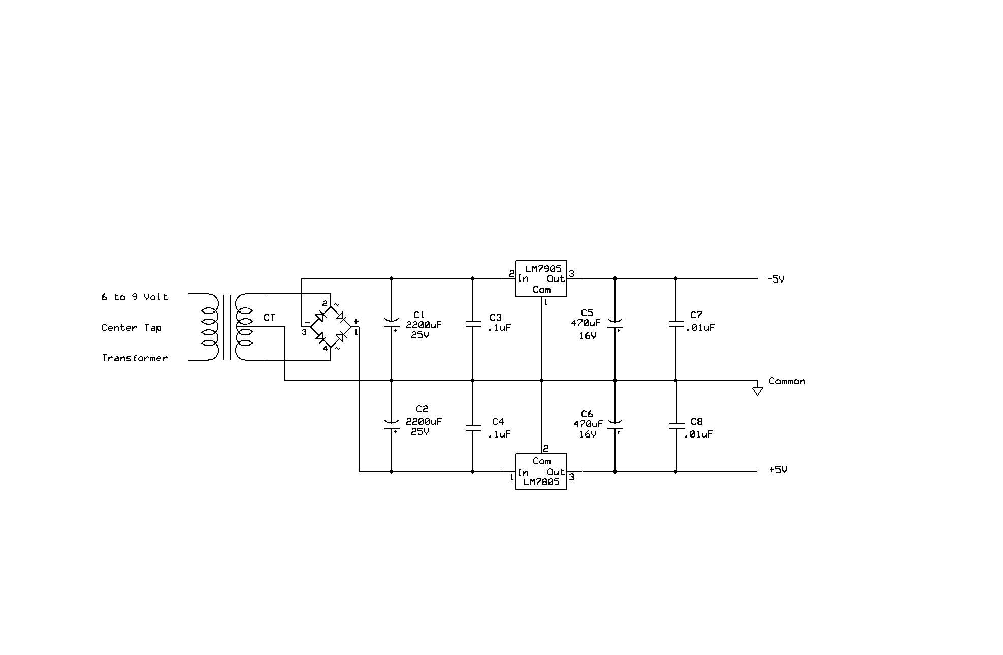
I want to build a +5 –5 Volt duel voltage power supply for use with op-amps
The attached schematic is the circuit I intend to build. My question
concerns the capacitors I have chosen to control ripple
·
Thank You
Mike
I want to build a +5 –5 Volt duel voltage power supply for use with op-amps
The attached schematic is the circuit I intend to build. My question
concerns the capacitors I have chosen to control ripple
·
Thank You
Mike
1975 x 1289 - 66K
Comments
2) On the output side of the regulator, I'd use 0.1uF capacitors. You could also use 470uF 6V capacitors since the output won't rise above 5V
3) You may need diodes to properly discharge the filter capacitors when the supply is turned off. There are examples in the datasheet for the regulator.
One question
when you said "You don't need quite as large an input capacitor" Did you mean Farad smaller or Voltage
Or both.
Thanks again
Mike w
I have attached a new schematic
Mike
▔▔▔▔▔▔▔▔▔▔▔▔▔▔▔▔▔▔▔▔▔▔▔▔ D Rat
Dave Ratcliff· N6YEE
Post Edited (ratronic) : 12/13/2008 4:35:36 AM GMT
Don't forget that the output voltage is expressed as across the whole winding, so you need at least a 20V center tapped transformer.
Vrms = (Vout*2 + Vdropout*2 + Vripple*2 + 2 *Vdiode)/1.4 = 10 + 4 + 4 + 1.4 = 20V
Here's a link for calculating the filter capacitor value: electronicdesign.com/Articles/Index.cfm?AD=1&ArticleID=9809
I was wrong about the filter capacitor value. It does need to be 2200uF for about a 300mA load.
If you increase the transformer voltage to 24V, you can double that load to about 700mA.
Mike actually when I was thinking transformers I was thinking 12 volt center tap or a 18 volt center tap
6 to 9 was a mental error I was thinking per side. As your formula pointed out I will consider my 18 or 24 v
transformers.
I havent tried your link yet but give me time
Mike
Whatever input voltage to the regulator that you finally settle on, remember that the regulator must dissipate the power caused by the current taken by the load and the voltage difference between the input voltage and the regulator output voltage...
In other words: RegPower = (VregIn - VregOut) * LoadCurrent
If I did the clacumlation on your example correctly, those regulators would be dissipating around 4 Watts each; way too much for use without a heat sink.
I snagged the following off of the National Semi website FAQs: (http://www.national.com/kbase/category/Power.html#254)
Why does my linear regulator get hot?
The regulator gets hot because it regulates the energy delivered to its load. A linear regulator drops an input voltage to a lower, regulated output, while conducting a current nearly equal to the load current. It must dissipate the excess energy, which is:
Pd = (Vin - Vout)*Iout (Pd is in Watts)
This energy is dissipated in the form of heat - the regulator die heats up above the ambient temperature with a temperature rise that''s proportional to the power dissipated, and to the thermal resistance from inside the die to the ambient environment:
Trise = Pd*ThetaJA (ThetaJA is in degC/Watt)
The die has an allowed Operating Rating for its internal temperature (junction temperature or Tj). If the temperature rise is too great, and the ambient temperature (Ta) is high, the junction temperature can exceed this rating, and the device will shut itself down. For most regulators, this maximum temperature is 125C (257F). Tj = Ta + Trise.
Relevant Part: REGULATOR
How can I keep the regulator cool?
The temperature rise can be minimized by reducing the thermal resistance. Thermal resistance is dealt with differently depending on whether the regulator is in a package that is designed to have a heat sink, or not. In both cases, the total thermal resistance is the sum of two parts:
1.Resistance from inside the die to the package surface or leads.
2.Resistance from the package surface or leads to the environment.
#1 is fixed, based on the die size and package type. #2 can be reduced by external heat sinking.
If the package is dual-in-line or surface-mount, the PC board is providing some heat sinking. This can reduce the total thermal resistance to about 60% of the thermal resistance seen with just a minimum of board area.
If the package is a power package with a metal tab, such as the TO-220, a heat sink can reduce the total thermal resistance to about 5-10% of the resistance seen with no heat sink.
If you search the web you'll be able to find "heat sink calculators" that will help in figuring out what size heat sink is required for your project.
Regards,
DJ
Post Edited (davejames) : 12/14/2008 3:44:05 AM GMT
Your stated objective is to power an op-amp or two, but your power supply could light a Christmas tree! There's a much less component-intensive and greener way to do this. Get a regulated switching wall transformer with a +5V output. To that, add a MAX660 voltage inverter to convert +5V to -5V at up to 100mA.
More to the point, though, why do you need the negative voltage? There is an abundance of op amp options that use a single supply. Many have rail-to-rail performance on both input and output. Even if your input swings negative, there are ways to bias the op-amp inputs to keep the signal within a positive common-mode range.
-Phil
Post Edited (Phil Pilgrim (PhiPi)) : 12/14/2008 4:22:15 AM GMT
The original circuit looks OK to me, though the capacitors are about 50 times larger than needed, which does no harm at all·-- and as noted in the correction, it ought to be about an 18vCT transformer.
▔▔▔▔▔▔▔▔▔▔▔▔▔▔▔▔▔▔▔▔▔▔▔▔
· -- Carl, nn5i@arrl.net
But as well-pointed out above, op amps require very very little power [noparse][[/noparse]but good quality - low noise], so the capacitance shouldn't be excessive at op amp loads.
Most op-amp really suffer with noisy switching supplies, not linear regulated supplies. The higher frequency appears harder to remove. Your ripple is anticipated to be 50/60 cps. The voltage regulator itself is very good at removing a lot of that ripple. Often the voltage regulator is specifically design to remove the 50/60 cps ripple.
Cooling. Again the question is really how much power are you dealing with? If 300ma is adequate, you may not need any heat sinks. The TO220 package is usually a 1amp regulator and runing at 1/3 capacity it isn't going to be running very hot. A 3 watt light bulb won't burn your fingers, so a 3 watt supply isn't going to be very hot either. Also, most of the regulators have thermal shut down. So if you have trouble, just add heat sinks later and it should function properly.
At the end of the day, the real question is at what scale are you providing power, 'How many watts?' And why so? Most of us tend to ponder a lot of engineering that is not required because we think we need a lot of power. But op amps amplify millivolts and output maybe a or two watt of power. Take a look at the spec sheets for the output and power rating of the op amp before you build something you regret.
But...
If you plan to further add a lot of op amps and/or power stages to get 20 or 100 watts beyond the op amp, then you need to start rethinking the whole design.
Phil is pretty much right on. These days even the little wall wart switch supplies are clean enough to run op-amps. I use one to run a TiniWebServer board at 5volts without regulation downstream and it hasn't messed up at all.
What has happen is the silicon chip 'switching regulators' have gotten better than the 'linear silicon regulators' and they don't produce all that wasted heat. It is only the old big boxy switchers that are likely to be too noisy. If you were to be using a old 350watt PC switcher to power op amps, you might have trouble. But maybe not. It would be interesting to try.
In all honesty, after designing and soldering tons of regulators and power supplies; I just have a PC switcher for heavy lifting with a couple of 20watt power resistors on the output to smooth the load. And I go an buy a little wall watt switcher for anything else. You can use a 5volt directly into an SX chip without any additional regulation. They also have 3.3volt ones.
Power supplies just are trivial accessories these days. Once upon a time, they were critical for prevention of glitches. For bench work, using a couple of AA battery packs to drive the OP-amps have no noise at all. Many people have gone a long way with op-amp by using two 9volt batteries as their sole supply.
Save your money to buy Parallax goodies that you really need.
▔▔▔▔▔▔▔▔▔▔▔▔▔▔▔▔▔▔▔▔▔▔▔▔
It's sunny and warm here. It is always sunny and warm here.... (unless a typhoon blows through).
Tropically, G. Herzog [noparse][[/noparse] 黃鶴 ] in Taiwan
I have to say one thing, my primary reason for selectig some of the components is that thoes are the ones I have in the draws in my shop.
any way thanks to all who chimed in
mike
Just to reiterate what PhiPi said above already, you don't need positive and negative voltage rails as there are ways to bias without. Here is an example circuit which will take an arbitrary ac signal and clamp it to 0-5v. There is a PGA output stage that probably doesn't make sense in your case, but the rest of the circuit might give you some ideas:
Referencing the attachment:
First, there is a capacitor with a switch. If the switch is open, the signal must pass through the cap, therefore no DC can get through. If the switch is closed, the cap is shorted, and thus DC can get through. Next is a resistive divider, R9, R10, and R11. This attenuates the signal by about 1/8 (close enough) and gives an input impedance of about 1 Megaohm (close enough). Then we have a buffer, IC2a. Next, the level shifting, where R5 and R6 provide the 2.5 volts that will serve as "ground" for the ADC, and IC2c buffers this. IC2a does the actual shifting. Note that 2.5v appears across R7 and R8, which means that 1.25v appears at V+ (the non-inverting input to the opamp). For an input of 0v (Ground) from the buffer, the op-amp will try to force both inputs to the same voltage, which means 1.25v at V- (the inverting input). To do this, it will put 2.5v on the output so that the feedback resistors (R3 and R4) will divide the voltage down to 1.25v at V-. Voila, 2.5 is the output for 0V input, and following similar logic you can see that an input of -2.5v will be bumped up to 0v and 2.5v will be bumped up to 5v.