

Quattro Gusti:- Pizza inspired microcomputing!
 Tubular
Posts: 4,774
Tubular
Posts: 4,774
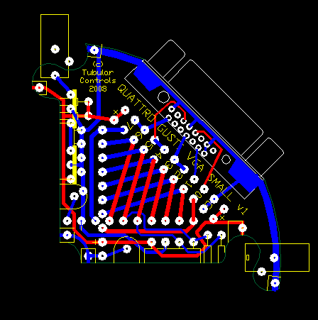
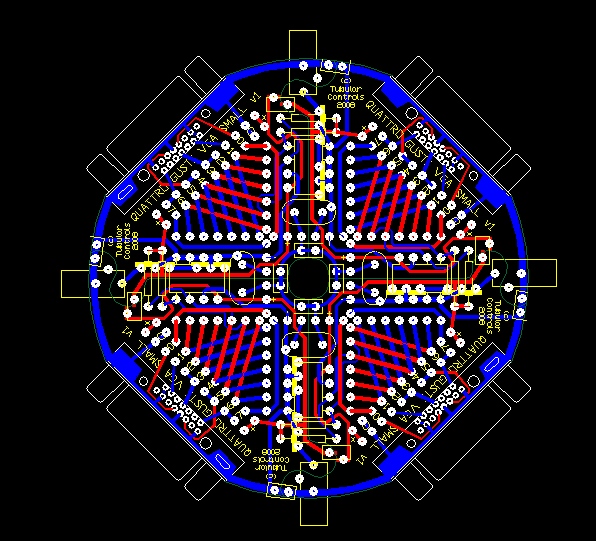
Quattro Gusti ("four corners") is a fun, simple and cheap pcb system for showing off the Prop.
Each of the four 'slices' can be any one of a number of I/O wedges (ps2, vga, sd card, usb, audio-video, and more). Once chosen, the dip40 is soldered in the middle, and holds it all together (glue logic, literally!)
I propose two sizes -
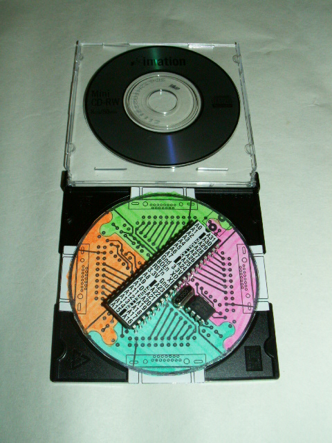
'Small' - 8cm diameter, same as a mini cd
'Large' - 12cm diameter, same as a standard cd/dvd, with Vesa75 mounting holes
however these could change slightly if I find a suitable case/tin/box.
I'll spec it up for open source soon so others can do their own wedge ('custom toppings'!) .
I need ideas for what to call the slices. Perhaps 'Margherita' could be the basics (programming header and ps2's). And something meaty for a motor driver. Suggestions welcome...
tubular.
Each of the four 'slices' can be any one of a number of I/O wedges (ps2, vga, sd card, usb, audio-video, and more). Once chosen, the dip40 is soldered in the middle, and holds it all together (glue logic, literally!)
I propose two sizes -
'Small' - 8cm diameter, same as a mini cd
'Large' - 12cm diameter, same as a standard cd/dvd, with Vesa75 mounting holes
however these could change slightly if I find a suitable case/tin/box.
I'll spec it up for open source soon so others can do their own wedge ('custom toppings'!) .
I need ideas for what to call the slices. Perhaps 'Margherita' could be the basics (programming header and ps2's). And something meaty for a motor driver. Suggestions welcome...
tubular.
448 x 451 - 18K
596 x 541 - 39K
480 x 640 - 202K

500 x 375 - 54K
Comments
Makes me hungry just looking at it [noparse];)[/noparse]
Are all the slices interchangable ?
Bean.
▔▔▔▔▔▔▔▔▔▔▔▔▔▔▔▔▔▔▔▔▔▔▔▔
- - - - - - - - - - - - - - - - - - - - - - - - - - - - - - -
"The welfare of the people in particular has always been the alibi of tyrants." ~ Camus
www.iElectronicDesigns.com
·
Yep, all slices are interchangable. They have a common set of circuitry which support the crystal/reset button, 5v reg, 3v3 reg, eeprom, pullups, and 1.3mm DC power jack.
So, just the I/O connector and passives vary between slices.
As usual it will be common for P24-31 to be used for programming and kb/ms.
Its only possible thanks to the symmetrical nature of the Dip40 layout... some good minds behind that methinks.
tubular.
▔▔▔▔▔▔▔▔▔▔▔▔▔▔▔▔▔▔▔▔▔▔▔▔
Timothy D. Swieter, E.I.
www.brilldea.com - Prop Blade, LED Painter, RGB LEDs, uOLED-IOC, eProto for SunSPOT, BitScope
www.tdswieter.com
Very nice... I like the idea. You could even color code different board options like you have it in the mockup.
Do you have other "anchor" solder points near the edges to keep the board aligned?
▔▔▔▔▔▔▔▔▔▔▔▔▔▔▔▔▔▔▔▔▔▔▔▔
Beau Schwabe
IC Layout Engineer
Parallax, Inc.
@Beau, I'm still in two minds about the color coding. Initially I was going to make it look like a pizza - red solder mask and perhaps some gold flash and yellow overlay. But having the quarters in different colors makes it stand out, because you don't see PCBs with a mix like that, so I'm leaning towards the different colors idea. I would love to find a pcb supplier with more than the 6 standard mask colors though.
The "anchors" definitely need attention. As shown in the photos, the plan was to use 2 pin, 0.1" headers with jumpers as these keep the boards flush as well as locked in laterally. My latest idea is to run the pcb split right through the middle PTH hole of the DC connector. The hole (or hole with dc pin in it) can then be filled with solder, which will flow across both halves of the hole. The DC connector itself would help keep the boards flush.
tubular.
My 2 cents
Marty
▔▔▔▔▔▔▔▔▔▔▔▔▔▔▔▔▔▔▔▔▔▔▔▔
Lunch cures all problems! have you had lunch?
I'm having trouble visualizing which side of the board, and for which prop (original and/or 2nd), you're proposing to add socket pins for. But either way there are some really exciting possibilities, so many thanks for the '2 cents worth'
1) If the second prop is placed above the original prop, on the same side of the board as the original prop, and stood off by your header socket pins, then the 'cornermost' 24 pins of the second prop easily connect to the board via the header pin sockets. Power, reset and the clock need to be wired through but this would be easy enough (4-6 wires to the raised second prop). The pins get translated somewhat, so second prop would be looking to boot off P4-P7 or P20-P23 of the original prop, depending on orientation. So the original prop could provide a bootloader to load the second prop.
2) If the second prop is placed on the reverse side of the original prop, again stood off by your header socket pins, you can potentially connect all 32 I/O pins through. You still have to wire the power because it works out to be reverse polarity on the reverse side. But the great news is the second prop would be trying to boot off P24-27 of the original propeller, which keeps the other 3 quadrants 'standard'.
Enlarging the DIP40 pads to more readily accept surface mount, or flattened standard socket pins, is also a great idea and I'll implement that to make soldering easier. You're right, it would certainly improve stability.
It really does my head in trying to work this through so I'll post an overlay drawing shortly to spare others the pain
Great suggestions, thanks Marty.
tubular.
It would indeed be great to be able to drag-and drop slices. A dream well worth pursuing. In fact it shouldn't be hard to write a script to blend the gerber files for 4 slices into one. So you wouldn't actually need a PCB package to generate a board. There is a great online gerber viewer here, and possibly a public pcb library too - http://www.circuitpeople.com/
The large slices should be large enough for basic prototyping. I might need to add some kind of generic connector on the 45 degree angle to help bring the nodes out in a friendly manner. The arc length of the large curved edge would be 9.4cm or 3.7" which is plenty for connectors.
tubular
tubular.
Question, why not make it either be based off a gas fit socket( So its snug). And a small lock(Maybe a bar crossing two sections, with screws in it). or something less permeant than soldering, then it would be a very quick rapid prototyping system. Have your pizza box, with all your slices in side, mix and match for what you want it to do, change of plan, change a slice.
Just a thought
TJ
8 props!? I'm struggling enough with getting my head around 2. Would you settle for connecting them in a 3x3 array?
I'd also like to make it as 'snappable' as possible, but there is a tradeoff with rigidity. At the moment as many components as possible span the joins to help keep it rigid. This is not good from the 'change of plan' point of view. However it is possible to socket everything, which might achieve what you want. Something is still required to link the power rails across, however. I'll try and keep that but simple and flexible so you can use, for example, a 0.1" jumper shunt
You'll have to explain the gas fit socket (perhaps with a link to a photo) - I'm not familiar with them ( at least I think I'm not )
As for the link bar I'm still looking for something cheap and small which keeps the slices co-planar. I'm thinking pcb spade lugs (at 4 cents) are not a bad option, but they needs soldering. And if you really don't want to solder theres always a Nal-clip...
tubular
Marty
▔▔▔▔▔▔▔▔▔▔▔▔▔▔▔▔▔▔▔▔▔▔▔▔
Lunch cures all problems! have you had lunch?
TJ
Edit* The 8 props was a joke, I have no idea what I would use 8 props for. Maybe a test of processing power, 3 would be very cool as well. Still not sure for what, I have a hard time using all 8 cogs on one prop per application. [noparse]:)[/noparse]
tubular.