

Interesting Project?
 -Gary
Posts: 6
-Gary
Posts: 6
Hello All!
· I recently joined your informative forum and enjoy reading the posts. Looking to gain some more electronic
know-how from BasicStamps. I have yet to start buying components and this is my reason for this post.
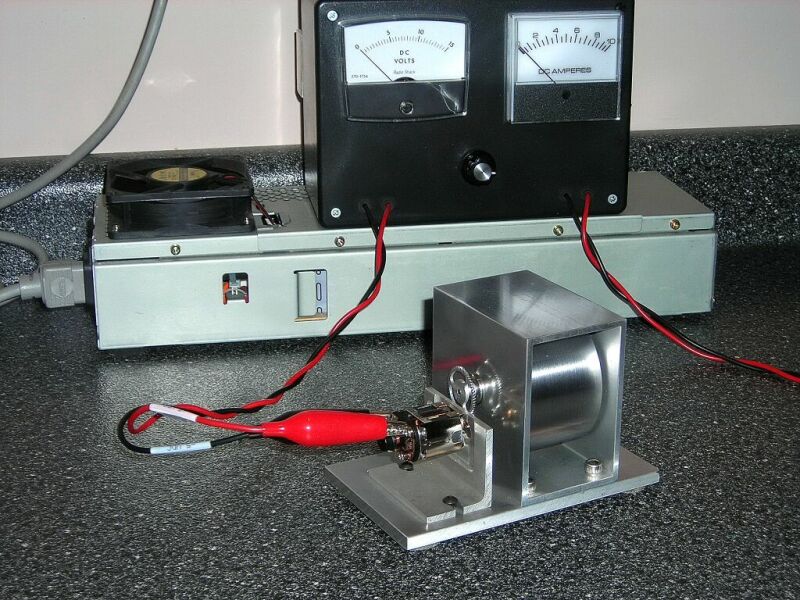
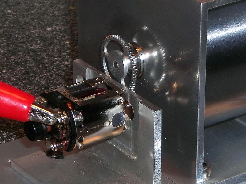
· My other hobby is racing slot cars and I was looking for a project to tie the two together. Thought about a
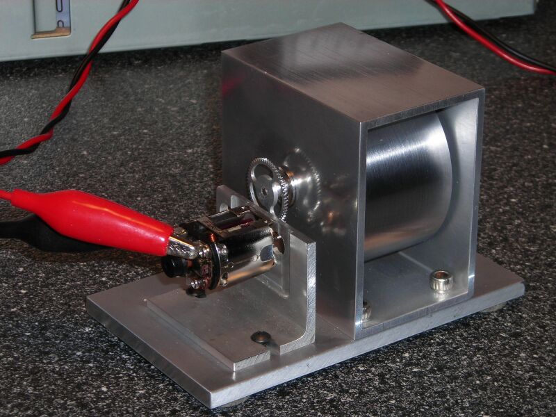
motor dyno, so I designed and built one (see attached photos). Will try to give a description of what I would
like to eventually achieve, maybe someone can get me started in the right direction.
Sequence of Operation:
· The controller (BS2?) would:
·· 1a.) Turn on a (solid state?) relay to power up the motor from my 12vdc PS.
·· 1b.) Start the BS2? timer at the same moment.
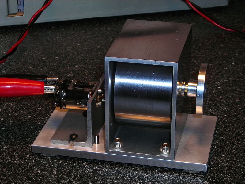
·· 2.) Controller would read flywheel pulses from sensor.
·· 3.) Controller would drop power to relay after a set time span. 6.0vdc takes 5 seconds to get max rpm.
······ Max Flywheel rpm would be calculated and displayed on a 2x16 LCD
·
Future Additions:
·· 1.) Every 0.25 sec. the controller would read flywheel pulses and store time and rpm data.
·· 2.) Data would be transferred to my desktop and displayed in Excel graph or maybe a VB program graph.
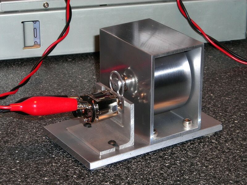
· I looked at a both a photo interrupter and Hall effect sensor to get an input. The photo interruptor looks
more usable due to balancing issue with the magnet. Has anyone found a compatible model with the stamps?
The motors can run about 20,000 rpm under load @ 6 vdc. I am using a 5.4:1 gear ratio which will limit my
rpm count to less than 3700·inputs per minute or 62 per second max.
Thanks in advance for your help!
·· -Gary
· I recently joined your informative forum and enjoy reading the posts. Looking to gain some more electronic
know-how from BasicStamps. I have yet to start buying components and this is my reason for this post.
· My other hobby is racing slot cars and I was looking for a project to tie the two together. Thought about a
motor dyno, so I designed and built one (see attached photos). Will try to give a description of what I would
like to eventually achieve, maybe someone can get me started in the right direction.
Sequence of Operation:
· The controller (BS2?) would:
·· 1a.) Turn on a (solid state?) relay to power up the motor from my 12vdc PS.
·· 1b.) Start the BS2? timer at the same moment.
·· 2.) Controller would read flywheel pulses from sensor.
·· 3.) Controller would drop power to relay after a set time span. 6.0vdc takes 5 seconds to get max rpm.
······ Max Flywheel rpm would be calculated and displayed on a 2x16 LCD
·
Future Additions:
·· 1.) Every 0.25 sec. the controller would read flywheel pulses and store time and rpm data.
·· 2.) Data would be transferred to my desktop and displayed in Excel graph or maybe a VB program graph.
· I looked at a both a photo interrupter and Hall effect sensor to get an input. The photo interruptor looks
more usable due to balancing issue with the magnet. Has anyone found a compatible model with the stamps?
The motors can run about 20,000 rpm under load @ 6 vdc. I am using a 5.4:1 gear ratio which will limit my
rpm count to less than 3700·inputs per minute or 62 per second max.
Thanks in advance for your help!
·· -Gary
800 x 600 - 148K
800 x 600 - 151K
800 x 600 - 123K
800 x 600 - 124K
800 x 600 - 114K
Comments
▔▔▔▔▔▔▔▔▔▔▔▔▔▔▔▔▔▔▔▔▔▔▔▔
Chris Savage
Parallax Engineering
· -Gary
One other option is PAUSE 6 seconds (or maybe a few more) to get the motor to speed and then COUNT.
Got a Discovery Kit from the Daily Deal ordered today.
Have you ever used a photo interrupter?
· -Gary