Shop OBEX P1 Docs P2 Docs Learn Events
No BASIC Stamps found. — Parallax Forums

No BASIC Stamps found.

cdcdcdcd Posts: 5
edited 2008-12-09 20:55 in BASIC Stamp
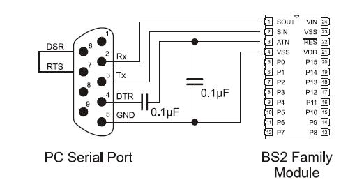
I have just begun trying to operate my basic stamp without a carrier board. I have the stamp in a breadboard with the proper power voltage across pins 23 and 24. My problem is with the serial connection. I am using the attached diagram to wire my serial cable to the breadboard. When I identify stamps or attempt to load a program, I get the error message "No BASIC Stamps found." COM1 sees an echo, but no loopback, and no stamp. I am not using COM2. Any ideas?
489 x 271 - 20K
bs.JPG 20.3K

Comments

  • allanlane5allanlane5 Posts: 3,815
    edited 2008-12-08 22:37
    Well, that looks pretty good, actually. What do you think is "Proper Voltage"? Because 5 volts across Vin and Vss isn't it, you need at least 6.

    The "no loopback" is a problem, because "Loopback" is supposed to be detecting that wire between the DB-9 pin 6 and 7. That your port isn't detecting that wire indicates some problem with your serial port. I mean, you can't get more simple than a dumb piece of wire.

    Are you perhaps using a "Null-Modem" cable? Are you using a USB to serial adapter?
  • cdcdcdcd Posts: 5
    edited 2008-12-08 22:44
    I have 13.6VDC across Vin and Vss.

    I am not using a USB to serial adapter. I am not using a null modem cable. I will investigate my connection between pins 6 and 7. Are you absolutely sure that a bad connection between pins 6 and 7 will result in the "no loopback" problem?
  • allanlane5allanlane5 Posts: 3,815
    edited 2008-12-08 23:09
    Did you make your own RS-232 cable then?

    And yes, I'm absolutely sure the "loopback" test is testing the presence (or absence) of that little piece of wire between pins 6 and 7. That's kind of a "raw hardware" test, that indicates you ARE using the right serial port, and that it IS physically connected to a BOE or Homework Board or at least connected to SOMETHING with pin 6 and 7 shorted together.

    Oh, and 13.6 volts DC (it IS DC, right?) should be just fine across Vin and Vss.·
  • FranklinFranklin Posts: 4,747
    edited 2008-12-09 02:04
    Without 'level shifters' in the data lines you are putting approximately 12 to 15 volts into pins made for 5 volts and will probably destroy your stamp!

    ▔▔▔▔▔▔▔▔▔▔▔▔▔▔▔▔▔▔▔▔▔▔▔▔
    - Stephen
  • Carl HayesCarl Hayes Posts: 841
    edited 2008-12-09 02:13
    I suggest temporarily tying pins 6 and 7 together (1) at the PC, and then (2) at the breadboard end of the cable, and seeing whether the Editor detects loopback in each of those cases (with the breadboard not connected to the cable). That will tell you (1) whether it's your COM1 port, and (2) whether it's your cable. If neither, it's a wiring error at your breadboard. This could be (a) a lack of connection between 6 and 7, or (b) unintended connection of both of them to something else in addition to each other -- either a wiring error or perhaps a solder bridge or the like. I suspect you may not have thought of (b).

    ▔▔▔▔▔▔▔▔▔▔▔▔▔▔▔▔▔▔▔▔▔▔▔▔
    · -- Carl, nn5i@arrl.net
  • Mike GreenMike Green Posts: 23,101
    edited 2008-12-09 02:14
    Franklin/Stephen,
    The Stamp SIN/SOUT/ATN inputs are designed for direct connection to an RS232 port. Look at the schematics in the Stamp Manual for details. The ATN needs the capacitors shown because most PCs hold the DTR line active the whole time the serial port is open and that will hold the Stamp in reset without the capacitors. With the capacitors, the Stamp resets on the leading and trailing edges only of the DTR signal.
  • Carl HayesCarl Hayes Posts: 841
    edited 2008-12-09 02:35
    Interesting, Mike. My examination of various third-party Stamp boards (I have a lot of them) shows that some of them omit the two capacitors and connect directly to the Stamp. One example is the Cool Key Accessories Stamp Controller Board, which works just fine. This has led me to omit the capacitors from my own PC boards, which also work just fine on at least five widely different PCs from Dell, from Toshiba, and homebuilt. Maybe it's just my good looks (actually I look a bit like your picture, but my beard is whiter), or maybe I'm very lucky.

    ▔▔▔▔▔▔▔▔▔▔▔▔▔▔▔▔▔▔▔▔▔▔▔▔
    · -- Carl, nn5i@arrl.net

    Post Edited (Carl Hayes) : 12/9/2008 2:40:19 AM GMT
  • allanlane5allanlane5 Posts: 3,815
    edited 2008-12-09 13:16
    No, omitting the capacitors WILL work fine -- UNTIL you try to use some program like Hyperterm, that holds DTR high (and therefore keeps the BS2 in reset).

    But if you don't use Hyperterm, you don't need the two capacitors.

    And yes, Mike is entirely correct, the SIN and SOUT pins do have 'level shifting' transistors on them which allow you to connect those pins directly to 'stock' +-12 volt RS-232 signals.

    For ANY OTHER I/O pin, you'll need a 22 Kohm resistor in series to prevent damage, if you're connecting directly to 'stock' RS-232 signals.
  • cdcdcdcd Posts: 5
    edited 2008-12-09 20:41
    Well, I resolved this problem. I don't know what I was doing wrong originally. I had a standard RS-232 cable with one end plugged into my computer's COM port, and the other plugged into a 9 pin D-sub connector. I soldered wires onto the end of the connector and plugged them into their proper place on the breadboard (connecting pins 6 and 7). Still, the editor did not detect a loopback.

    So I cut my serial cable in half to create a pigtail, used a multimeter to determine which color wire corresponded to each pin, and plugged the wires directly into the breadboard (didn't bother with the capacitors). Now, both the echo and loopback, as well as the stamp itself, are detected by the editor, and hello world works.

    Thanks for everyone's help!
  • allanlane5allanlane5 Posts: 3,815
    edited 2008-12-09 20:55
    Yay! Glad you got it working.
Sign In or Register to comment.