

New project: LED sign
 Ugha
Posts: 543
Ugha
Posts: 543
I've recently received a programmable LED sign and have a few ideas for uses for it.
Unfortunately it requires either a DOS computer and special software, or a special keyboard built
for the purpose.
I'd like to just use the LED board, not the control board, and hook it up to a stamp and use
that to control the LED array.
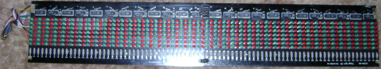
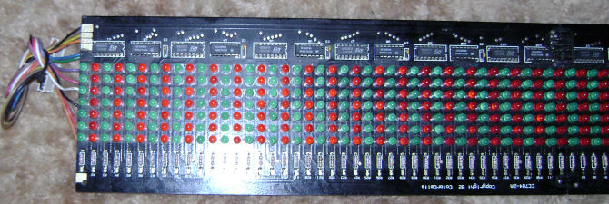
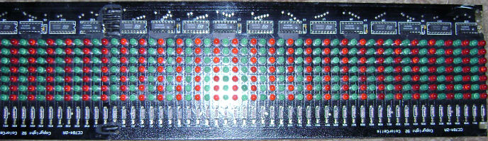
The board has 588 LEDs arrayed in a 7x84 matrix of some kind.
There are 82 100 ohm resistors, 12·tiny capacitors that are so small I can't make out the markings
on them without desoldering them.
There are 12 SN74LS164N serial-in, parallel-out shift registers and 12 ULN2003A seven darlington arrays.
7 wires come off one section of the board, the circuit board has·a single trace for each of them that
spans one lead of each led. I'm assuming these are common grounds or supplies.
There are also six other wires coming off of the section where the ICs are... although two pairs are connected
together (shared grounds or supplies for the ICs?).
I've attached the datasheets for the two ICs and I kind of understand them, but I don't get exactly
how everything works together.
I've also attached some photos of the board in case anyone feels up to the challenge of helping a
newbie figure this thing out.
Post Edited (Ugha) : 12/6/2008 10:01:54 PM GMT
Unfortunately it requires either a DOS computer and special software, or a special keyboard built
for the purpose.
I'd like to just use the LED board, not the control board, and hook it up to a stamp and use
that to control the LED array.
The board has 588 LEDs arrayed in a 7x84 matrix of some kind.
There are 82 100 ohm resistors, 12·tiny capacitors that are so small I can't make out the markings
on them without desoldering them.
There are 12 SN74LS164N serial-in, parallel-out shift registers and 12 ULN2003A seven darlington arrays.
7 wires come off one section of the board, the circuit board has·a single trace for each of them that
spans one lead of each led. I'm assuming these are common grounds or supplies.
There are also six other wires coming off of the section where the ICs are... although two pairs are connected
together (shared grounds or supplies for the ICs?).
I've attached the datasheets for the two ICs and I kind of understand them, but I don't get exactly
how everything works together.
I've also attached some photos of the board in case anyone feels up to the challenge of helping a
newbie figure this thing out.
Post Edited (Ugha) : 12/6/2008 10:01:54 PM GMT

753 x 138 - 69K
670 x 225 - 91K
688 x 199 - 99K
Comments
may be useful.
Take a look in the SX forum at what " T&E Engineer " posted.
"Sneak peek-LED sign"
I thank it might be of some help.
________$WMc%_____Merry Xmas___
▔▔▔▔▔▔▔▔▔▔▔▔▔▔▔▔▔▔▔▔▔▔▔▔
The Truth is out there
Post Edited ($WMc%) : 12/7/2008 1:15:19 AM GMT
▔▔▔▔▔▔▔▔▔▔▔▔▔▔▔▔▔▔▔▔▔▔▔▔
Chris Savage
Parallax Engineering
I've attached the manual for the sign in case anyone felt up to helping me out on this.
Again, I want to hook this up to a BS2 or if I must, an SX.
I don't want to desolder the LEDs, or use the existing controller board. I'd like to
interface with the existing light board using a stamp and try and get it to work.
Any help at all would be much appreciated.
If you don't want to use the LED controller, the documentation for it doesn't help at all. It looks like you'll have to use the existing controller or trace through the PCB to come up with a schematic. Like you said, it's probably a matrix arrangement of some sort. How to drive it without using the existing controller is anybody's guess until there's a schematic, at least enough of one to figure out how it's all hooked together.
You should be able to drive it with a Stamp since it probably just has to handle the cascaded shift registers, but you'll have to verify that and figure out the format of the data.
Post Edited (Mike Green) : 12/7/2008 11:01:44 PM GMT