

Propeller Controlled Reflow Oven
 Timothy D. Swieter
Posts: 1,613
Timothy D. Swieter
Posts: 1,613
I have gotten my project to a point that I can show it off. My latest projects, which has taken a couple weekends longer than I anticipated, is a reflow oven for surface mount soldering built out of a standard toaster oven. This project incorporates a Propeller USB Protoboard and the Parallax Thermocouple kit as well as the Brilldea Graphical LCD display.
For some time I have done all my surface mount soldering by hand. Soldering by hand is an OK and works well for some parts. Of course there are leadless parts that you can't really hand solder with any success. Also, hand soldering takes time and if I am going to produce more than one or two assemblies I don't really want to hand solder that many SMT parts. Therefore I decided to buid a reflow oven. There are several great resources on the web and in magazines dealing with this topic. I sought those out and studied them before I started this project.
The project isn't finished yet. The hardware is complete, but the software has several components missing. Enough is there though that I can reflow a board. I did a test board the other day and the test went fine. Now I need to get some tools for applying the soldering paste - namely fine point needles for the syringe I have.
In time I hope to post a PDF or Instructables about the build. For now I will post some details here and several pictures:
Toaster Oven: The appliance was purchased at a local electronics store. I shopped around for all the different toaster ovens offered and considered each one. Ultimately I wanted one with a wattage and a low volume. After my research and reading I also decided I should get a convection oven (a fan to move the air around to ensure consistent temps). I am not convinced that this is needed as it added a lot to the price tag of the oven, but I have it now. My oven is 12.5 liters internal volume and I believe it is 1600 watts. The oven has a double rack so at some point I may try "toasting" boards on multilevels.
Thermocouple: I used the Parallax Thermocouple kit for sensing the temperature in the oven. I drilled a hole in the top and fed in the thermocouple. The electronics portion is kept in a plastic box on the outside of the oven and a cable with the one-wire signal and power is fed to the controller.
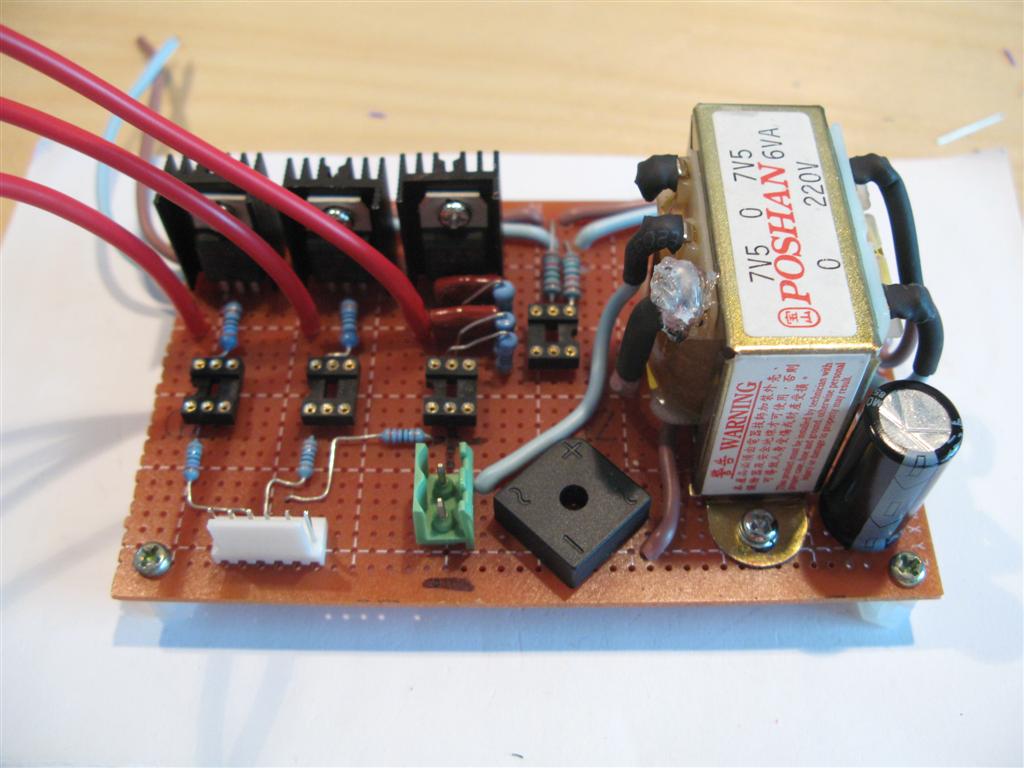
AC controls: I used three triacs and a zero-crossing detection for the AC control portion of the circuit. I decided to use triacs because I wanted to experiment with varying the intensity level. Also the traics take up less space than a couple mechanical relays or solid state relays would. Of course there is more wiring and soldering with triacs and a little more code. I used a couple references on-line for the triac and zero-crossing circuit. The main reference was an article in Nuts&Volts by Jon a year or two ago on controlling Christmas Lights with the SX. That article helped for both the theory and the setup of the triacs.
User Interface: The user interface consists of a graphical LCD display, a couple push buttons, a couple LEDs and a piezo speaker. The GUI is setup like an iPOD GUI. The buttons move the cursor up or down or selects the highlighted entry. Also there is a back button. The LED indicate the controller is on or that the controller is doing a reflow. The piezo makes clicks and pops for confirming inputs or warnings.
Power: The controller and toaster oven are powered by AC. There is a transformer and rectifier for making DC for the Propeller USB Protoboard.
Propeller: The Propeller is the brains behind the controller. There is a Cog for controlling the LEDs and debouncing the buttons. There is a cog for the thermocouple and a cog for the one-wire communication (from object exchange). The thermocouple code still has some problems that I don't understand but hopefully in time I or someone can figure it out. There is a cog for the LCD driver and a cog for the graphics routines. There is the main loop cog as well. Oh and a cog for the triac control. Of course I am not ready to post the code yet being that the code is half there and there are the menu functions that I need to add.
How about some pictures?
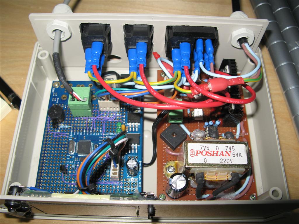
IMG_8537: The AC board for triac control, zero-crossing detection and rectifying. Shown without the ICs installed.
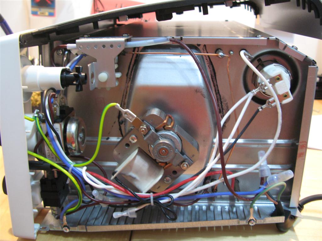
IMG_8579.jpg: The side of the toaster oven before modifications. I mostly ripped out all the wires and rewired the heaters to one plug, the internal light to another plug and the convection fan to yet another plug.
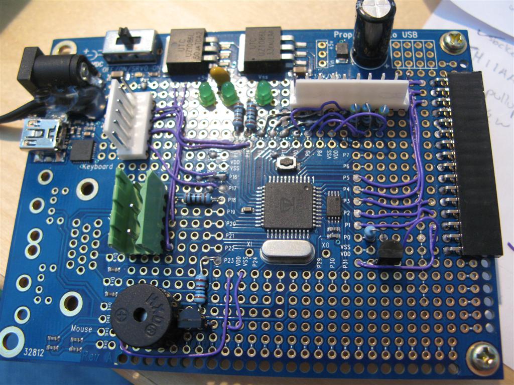
IMG_8596.jpg: The Propeller Protoboard with added connectors and circuits.
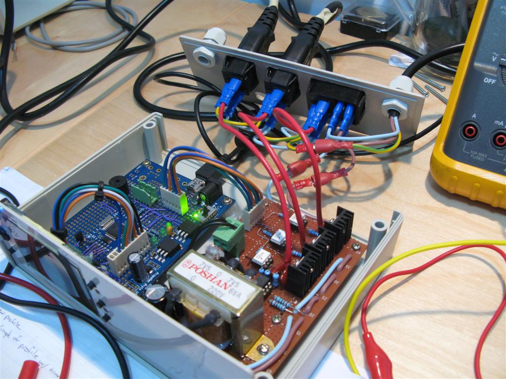
IMG_8608.jpg: The controller during testing.
IMG_8980.jpg: Another picture of the controller
▔▔▔▔▔▔▔▔▔▔▔▔▔▔▔▔▔▔▔▔▔▔▔▔
Timothy D. Swieter, E.I.
www.brilldea.com - Prop Blade, LED Painter, RGB LEDs, uOLED-IOC, eProto for SunSPOT, BitScope
www.tdswieter.com
Post Edited (Timothy D. Swieter) : 12/1/2008 12:57:21 AM GMT
For some time I have done all my surface mount soldering by hand. Soldering by hand is an OK and works well for some parts. Of course there are leadless parts that you can't really hand solder with any success. Also, hand soldering takes time and if I am going to produce more than one or two assemblies I don't really want to hand solder that many SMT parts. Therefore I decided to buid a reflow oven. There are several great resources on the web and in magazines dealing with this topic. I sought those out and studied them before I started this project.
The project isn't finished yet. The hardware is complete, but the software has several components missing. Enough is there though that I can reflow a board. I did a test board the other day and the test went fine. Now I need to get some tools for applying the soldering paste - namely fine point needles for the syringe I have.
In time I hope to post a PDF or Instructables about the build. For now I will post some details here and several pictures:
Toaster Oven: The appliance was purchased at a local electronics store. I shopped around for all the different toaster ovens offered and considered each one. Ultimately I wanted one with a wattage and a low volume. After my research and reading I also decided I should get a convection oven (a fan to move the air around to ensure consistent temps). I am not convinced that this is needed as it added a lot to the price tag of the oven, but I have it now. My oven is 12.5 liters internal volume and I believe it is 1600 watts. The oven has a double rack so at some point I may try "toasting" boards on multilevels.
Thermocouple: I used the Parallax Thermocouple kit for sensing the temperature in the oven. I drilled a hole in the top and fed in the thermocouple. The electronics portion is kept in a plastic box on the outside of the oven and a cable with the one-wire signal and power is fed to the controller.
AC controls: I used three triacs and a zero-crossing detection for the AC control portion of the circuit. I decided to use triacs because I wanted to experiment with varying the intensity level. Also the traics take up less space than a couple mechanical relays or solid state relays would. Of course there is more wiring and soldering with triacs and a little more code. I used a couple references on-line for the triac and zero-crossing circuit. The main reference was an article in Nuts&Volts by Jon a year or two ago on controlling Christmas Lights with the SX. That article helped for both the theory and the setup of the triacs.
User Interface: The user interface consists of a graphical LCD display, a couple push buttons, a couple LEDs and a piezo speaker. The GUI is setup like an iPOD GUI. The buttons move the cursor up or down or selects the highlighted entry. Also there is a back button. The LED indicate the controller is on or that the controller is doing a reflow. The piezo makes clicks and pops for confirming inputs or warnings.
Power: The controller and toaster oven are powered by AC. There is a transformer and rectifier for making DC for the Propeller USB Protoboard.
Propeller: The Propeller is the brains behind the controller. There is a Cog for controlling the LEDs and debouncing the buttons. There is a cog for the thermocouple and a cog for the one-wire communication (from object exchange). The thermocouple code still has some problems that I don't understand but hopefully in time I or someone can figure it out. There is a cog for the LCD driver and a cog for the graphics routines. There is the main loop cog as well. Oh and a cog for the triac control. Of course I am not ready to post the code yet being that the code is half there and there are the menu functions that I need to add.
How about some pictures?
IMG_8537: The AC board for triac control, zero-crossing detection and rectifying. Shown without the ICs installed.
IMG_8579.jpg: The side of the toaster oven before modifications. I mostly ripped out all the wires and rewired the heaters to one plug, the internal light to another plug and the convection fan to yet another plug.
IMG_8596.jpg: The Propeller Protoboard with added connectors and circuits.
IMG_8608.jpg: The controller during testing.
IMG_8980.jpg: Another picture of the controller
▔▔▔▔▔▔▔▔▔▔▔▔▔▔▔▔▔▔▔▔▔▔▔▔
Timothy D. Swieter, E.I.
www.brilldea.com - Prop Blade, LED Painter, RGB LEDs, uOLED-IOC, eProto for SunSPOT, BitScope
www.tdswieter.com
Post Edited (Timothy D. Swieter) : 12/1/2008 12:57:21 AM GMT
1024 x 768 - 88K
1024 x 768 - 110K
1024 x 768 - 172K
1024 x 768 - 142K
1024 x 768 - 140K
Comments
IMG_8835: The board after reflowing. As suspected there were be some problems, but for the most part it worked. IT WORKED!!!
IMG_8629.jpg: The thermocouple in its housing.
IMG_8989.jpg The oven and controller setup in my home office. Space is really at a premium now.
▔▔▔▔▔▔▔▔▔▔▔▔▔▔▔▔▔▔▔▔▔▔▔▔
Timothy D. Swieter, E.I.
www.brilldea.com - Prop Blade, LED Painter, RGB LEDs, uOLED-IOC, eProto for SunSPOT, BitScope
www.tdswieter.com
Post Edited (Timothy D. Swieter) : 12/1/2008 12:58:05 AM GMT
IMG_8998.jpg The menu selection. The ">" indicates there is a sub menu - like an iPOD. The buttons on the right navigate the highlight up and down and the middle button is the select. The button on the lower left is a back button.
IMG_8774.jpg: A screen shot while the oven is running through a profile.
▔▔▔▔▔▔▔▔▔▔▔▔▔▔▔▔▔▔▔▔▔▔▔▔
Timothy D. Swieter, E.I.
www.brilldea.com - Prop Blade, LED Painter, RGB LEDs, uOLED-IOC, eProto for SunSPOT, BitScope
www.tdswieter.com
Post Edited (Timothy D. Swieter) : 12/1/2008 12:58:35 AM GMT
I'd love to send this thread to Hackaday for a little well-deserved recognition, (they would love it!)
but last time I did it it really brought out the trolls. [noparse]:)[/noparse]
Nice Job!
Serious question: How does doing reflow with this differ from simply heating up an unmodified oven
and attempting to do the same thing? Other than temperature, what has to be carefully controlled for
this to work correctly? (Asked from a perspective of no understanding of reflow systems.)
OBC
▔▔▔▔▔▔▔▔▔▔▔▔▔▔▔▔▔▔▔▔▔▔▔▔
New to the Propeller?
Getting started with a Propeller Protoboard?
Check out: Introduction to the Proboard & Propeller Cookbook 1.4
Updates to the Cookbook are now posted to: Propeller.warrantyvoid.us
Got an SD card connected? - PropDOS
I don't mind if you want to submit forum thread. In time I am going to work up an Instructables and would consider submitting that. I know that there are several other toaster oven projects out there and this is not unique per se. The Propeller is a unique part it. I also think the nice looking GUI is a good part too.
There was one or two pages I found where someone has used an unmodified oven. Yes you can make it work, but it would take a couple trials to figure out the right recipe for time and temp. There is a solder curve or solder profile that the board/components and paste should go through. This profile should be roughly followed. There is a maxim temperature for reflow and before that there is bringing all of the parts up to a consistent temperature. With my setup there is a tighter control of the temp and the process because of the feedback. It still isn't perfect, but there can be repeatable performance. If you are going to be doing ones and twos, sure go ahead and try it in a garage sale toaster oven. Get a little timer to track time and give it a go. I bet it would work, but for consistent use or production use I would recommend trying to have a better system on it. Does this help OBC?
▔▔▔▔▔▔▔▔▔▔▔▔▔▔▔▔▔▔▔▔▔▔▔▔
Timothy D. Swieter, E.I.
www.brilldea.com - Prop Blade, LED Painter, RGB LEDs, uOLED-IOC, eProto for SunSPOT, BitScope
www.tdswieter.com
That does clear up the process for me. [noparse]:)[/noparse] How much times does the who process take from start to finish?
OBC
▔▔▔▔▔▔▔▔▔▔▔▔▔▔▔▔▔▔▔▔▔▔▔▔
New to the Propeller?
Getting started with a Propeller Protoboard?
Check out: Introduction to the Proboard & Propeller Cookbook 1.4
Updates to the Cookbook are now posted to: Propeller.warrantyvoid.us
Got an SD card connected? - PropDOS
▔▔▔▔▔▔▔▔▔▔▔▔▔▔▔▔▔▔▔▔▔▔▔▔
Whit+
"We keep moving forward, opening new doors, and doing new things, because we're curious and curiosity keeps leading us down new paths." - Walt Disney
Wow, 12.5 liters is more than just a toaster oven! What make and model is it? Is it infrared? I think you'll be glad you got the convection feature. My little fanless IR oven tends to burn large boards, which I ascribe to the lack of airflow around them.
-Phil
I've hand soldered leadless components (not BGA though) using solder paste and a hot air blower. The process feels terrible - I always think it's amazing that it works at all - but so far I've had remarkably good success.
I think that once you have a reflow oven, there are still tricks to learn.
With hand soldering the age of the solder paste doesn't seem to matter too much - mine is three years out of date and still works fine. But, it proved to be unreliable in the reflow oven - with a fair amount of tombstoning and solder that simply didn't even melt properly. I think I might need to invest in a tube of fresh paste, but don't know that I'll ever do enough soldering to us it in the six months that's normally specified for the paste.
I think that having a solder paste stencil would also be a good idea, as it is hard to get consistent "laying" of the paste by hand. I use a 3ml syringe (which holds enough paste for many hundreds of joints) and a jewellers screw driver to smear the paste onto the pads. This works okay for a solder-by-hand process.
▔▔▔▔▔▔▔▔▔▔▔▔▔▔▔▔▔▔▔▔▔▔▔▔
I spent 18 months in an assembly house where we had SMT robots and through hole as well. Unfortunately I didn't really get to undestand much about reflow innards, but I can add this to the discussion.... Some of this is basic and may already be known, but for those that don't here goes (and please correct anything that may be wrong - I am not an expert at this)
The oven has a conveyor belt. The pcb must have a ramp up temperature, a old temperature and a ramp down temperature. There is a maximum time and temperature that ICs can handle and this must be observed if you do not want premature failure of components. All this should be available somewhere on manufacturers websites.
To get extended life from your solder paste, keep it in the fridge. If you use a needle to inject to the pcb, remove and clean the needle and cap the syringe. When you next use the syringe, discard the first bit of paste.
In the early 80's, I saw a guy make a solder paste dispenser from an old printer and a syringe and small pump. It could be worth a try as I am sure the prop would make this much easier than it was then.
Hand SMT machines (used) may be available cheap on places like eBay. Components are placed with a tool with a foot operated suction pump and a tube coming out of the end of a soldering iron like tool with a rubber end that is flattened (looks something like the plastic isolator rings used on TO220 transistors). Maybe these ends can be purchased as spares for a production tool???
Unfortunately, a solder paste stencil is expensive (or was 5 years ago) so I don't think this is an option for small production. (correct me if this has changed).
Now for a question - I have been out of the industry for a while - who can explain the differences in lead-free soldering techniques ??
▔▔▔▔▔▔▔▔▔▔▔▔▔▔▔▔▔▔▔▔▔▔▔▔
We used to marvel at Maxwell Smart·having a phone in his shoe. Now we just say what a stupid place to put a phone!
@TChapman: Wow that is a nice interface! Do you have your own reflow oven? Are you cooking up a little project? I considered doing a VB or similar program but I don't always want my computer attached to the controller. I also wanted to create a project using the Graphical LCD so I had examples of it in use. Boy it looks like your interface has all the right controls for temp, degrees per second, phases - all of it. Nice work!
@OBC: the reflow process can take from four to 6 minutes and that doesn't include the full cool down to the point where the board can be handled. There is a profile that is shown in data sheets and online for soldering. The profile is usually broken down into four or five stages. The name of the stages can vary. The first stage is preheat in which the temperature gets to its first set point and holds for a while. Then there is the soak in which the temperature get to a point that the fluxs flows out of the solder paste. This temperature is also held for a while to ensure the board and components are at an equal temperature. Then there is the reflow or soldering stage when the temperature is taken above the solder melting point for a short time. This time can be from 30 to 60 seconds. Then there is a holding time when the temp drops, but not too fast. Then the cool down stage in which the temp drops.
@Phil: I was looking mainly at ovens in the 10 to 12.5L range. All the smaller ovens were really small and cheap feeling. Yes the oven is infrared/heater - aren't all toaster ovens like this? Maybe I am getting my terms confused here. The maker of the oven is Delonghi. The model is EO1252W. And I have a correction to my first post, the oven is actually 1400Ws - not 1600 like I quoted. This gives me around 112W/L. Overall I thought the oven would heat a little faster than it does but that was just a thought and nothing really to base my expectation on. I am looking forward to doing more boards to see how the convection features helps out.
@Mirror: Yeah I imagine there are tricks and techniques to learn yet. Maybe I don't know what I am getting myself into, but so far it is exciting. I looked briefly at the reflow oven on Ebay and available here in HK, but I wasn't so sure of them. I also saw that Elektor has a reflow oven they sell and certified, but they want a considerable amount for the oven.
@Cluso99: Yep, I have seen several PCB fab houses both small size and gigantic ones turning our PS3s. My little table top toaster oven reflow pales in comparison to the 7 stage ovens I have seen in big fab houses. You offer several good tips, thank you. Solder stencils can be expensive, but that depends where and how you buy them. A couple years ago Sparkfun posted about their experience. They have been buying solder stencils made of mylar (I think) and cut on a laser. The stencils cost US$25 or so I believe. I need to look back into this. With Lead-free soldering the reflow process is similar, but the temperatures are generally higher than with lead-based soldering.
▔▔▔▔▔▔▔▔▔▔▔▔▔▔▔▔▔▔▔▔▔▔▔▔
Timothy D. Swieter, E.I.
www.brilldea.com - Prop Blade, LED Painter, RGB LEDs, uOLED-IOC, eProto for SunSPOT, BitScope
www.tdswieter.com
I guess the distinction I was trying to make with "IR" is that the units advertised as such have straight-line quartz heating elements, a opposed to nichrome ribbon or those serpentine black things that glow red. In any event, it looks like you've really got a nice setup!
-Phil
▔▔▔▔▔▔▔▔▔▔▔▔▔▔▔▔▔▔▔▔▔▔▔▔
'Just a few PropSTICK Kit bare PCBs left!
www.sparkfun.com/commerce/tutorial_info.php?tutorials_id=59
▔▔▔▔▔▔▔▔▔▔▔▔▔▔▔▔▔▔▔▔▔▔▔▔
·"I have always wished that my computer would be as easy to use as my telephone.· My wish has come true.· I no longer know how to use my telephone."
- Bjarne Stroustrup
The reflow I've got originated in HK. It's got menu options for lead as well as lead free solder pastes, and you can also enter a custom temperature curve. It seems to do everything it should, ramp-hold-solder-cool. The oven menu and instruction manual are a bit "Chinese", but other than that I have no complaints.
By the way I also have a toaster oven, but for a completely different reason - it hasn't been modified at all. Some parts are moisture sensitive, and I suspect that this will be an even bigger problem when using a reflow oven. I use the toaster oven to bake moisture sensitive parts at about 80C for about 24 hours. Initially I thought that power consumption might be a problem, but the oven seems to idle along at about 30W average once the temperature has stabilised.
Cluso mentioned a manual pick and place tool - I don't mind using tweezers and a desk magnifying lamp. Something that I think would be a handy alternative to stencils is a foot operated solder paste dispenser. It's on my wish list - which always seems to extend further than my budget.
▔▔▔▔▔▔▔▔▔▔▔▔▔▔▔▔▔▔▔▔▔▔▔▔
@Ken: I have read those tutorials are SparkFun and they are very educational. I first investigated doing the reflowing in an electric pan like they did, but wouldn't you know it that I can't get a simple electric frying pan here? I looked and looked and didn't see anything cheap. They all had these fancy controls and such or were designed specifically for use with woks and were expensive.
@Mirror: You know, I wish more products could be customized. Like the reflow oven you bought, I wish there was an interface so that one could write their own process routines or adjust the LCD display to be what they want. I guess this is just the "maker" inside of me wanting to be able to customize the products to my needs and desires.
For pick and place at the moment I use tweezers and little hand operated vacuum pumps, but mostly tweezers.
▔▔▔▔▔▔▔▔▔▔▔▔▔▔▔▔▔▔▔▔▔▔▔▔
Timothy D. Swieter, E.I.
www.brilldea.com - Prop Blade, LED Painter, RGB LEDs, uOLED-IOC, eProto for SunSPOT, BitScope
www.tdswieter.com
One of the early pick and place tools was just a small metal tube through a handle with a foot operated suction pump. The component end was bent and terminated in a rubber piece as I described above (I am sure the rubber piece could be purchased from a SMT tools supplier). I have seen metal tubes in the model aircraft shop that may suit.
Some of the SMT rework stations just use heat via a tube delivery system to blow hot air onto the pcb. It would need to be low volume flow and temperature controlled. This is just "food for thought".
A significant part of the cost of stencils is the frame. In small quantities this can be avoided.
Has anyone had any experience with ball grids??? I would love to try one.
▔▔▔▔▔▔▔▔▔▔▔▔▔▔▔▔▔▔▔▔▔▔▔▔
We used to marvel at Maxwell Smart·having a phone in his shoe. Now we just say what a stupid place to put a phone!
But that shouldn't stop anyone attempting to have 'fun'.
▔▔▔▔▔▔▔▔▔▔▔▔▔▔▔▔▔▔▔▔▔▔▔▔
Harley Shanko
(with some very nice pictures)
For Rework: cgi.ebay.com/IRDA-Infrared-Desoldering-Rework-Station-Welder-2-Bulb_W0QQitemZ310086443070QQcmdZViewItemQQptZBI_Soldering?hash=item310086443070&_trksid=p3911.c0.m14&_trkparms=72%3A1205|66%3A2|65%3A12|39%3A1|240%3A1318
(with a video you can download)
Graham
▔▔▔▔▔▔▔▔▔▔▔▔▔▔▔▔▔▔▔▔▔▔▔▔
Timothy D. Swieter, E.I.
www.brilldea.com - Prop Blade, LED Painter, RGB LEDs, uOLED-IOC, eProto for SunSPOT, BitScope
www.tdswieter.com
Graham: echo "Neat Idea"
▔▔▔▔▔▔▔▔▔▔▔▔▔▔▔▔▔▔▔▔▔▔▔▔
We used to marvel at Maxwell Smart·having a phone in his shoe. Now we just say what a stupid place to put a phone!