Shop OBEX P1 Docs P2 Docs Learn Events
Zener mystery. — Parallax Forums

Zener mystery.

T ChapT Chap Posts: 4,223
edited 2008-12-01 23:06 in General Discussion
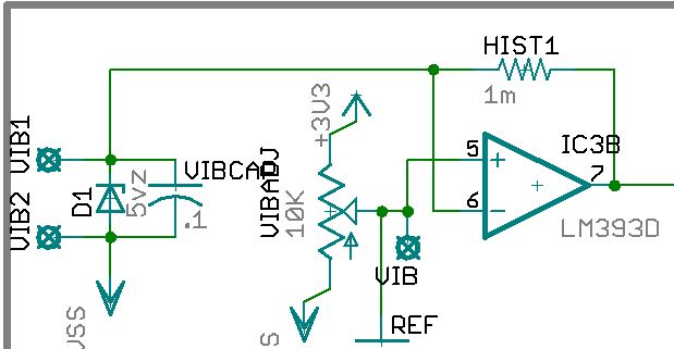
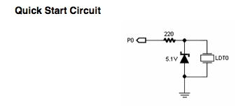
I took the similar circuit shown on the Parallax Piwzo Vibra Tab pdf shown below, I only added a cap so that I could adjust the response if desired.

Shown is my exact board design, but there is a strange thing. Without using the Vbra tap, just applying a voltage from 0 - 3v3 from a Prop DAC (10k, .01cap), the voltage after the 10k which feeds the - input of the comparator is never higher that .686v, even if the input is 3v3. So I assumed the 5v1 zener was in backwards, and reversed it, then I can apply whatever voltage I want up to 3v3.

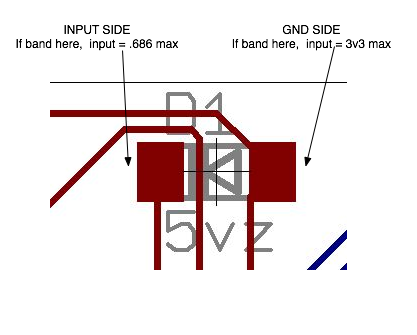
I checked the package to verify cathode is the marked side, I checked the symbol too, these are stock Eagle library parts.

What am I missing with this? Surely the zener should allow up to 5.1v to pass through?

I am questioning if the current limiting resistor off the DAC is causing the result.

search.digikey.com/scripts/DkSearch/dksus.dll?lang=en&site=US&keywords=FLZ5V1CCT-ND&x=0&y=0

Post Edited (TChapman) : 11/30/2008 10:27:47 PM GMT
619 x 321 - 31K
340 x 155 - 7K
417 x 335 - 36K

Comments

  • Phil Pilgrim (PhiPi)Phil Pilgrim (PhiPi) Posts: 23,514
    edited 2008-11-30 22:46
    Something doesn't add up here. If you're seeing anything in the neighborhood of a 0.6V limit, it means the zener's in backwards. Perhaps you could show us more of your layout?

    Also, I note that the feedback resistor on your LM393 comparator is labeled "HIST1". If this is meant to be a hysteresis resistor, it needs to go to the positive input, not the negative input.

    -Phil
  • T ChapT Chap Posts: 4,223
    edited 2008-11-30 23:09
    Thanks Phil, yes it is very strange, but I checked the zener datasheet, and went over the library parts, the cathode marking is the band, the symbol shows the arrow to the cathode. The datatsheet shows the color band on the cathode.

    Here are more pics. I reversed the hyst resistor.
    652 x 423 - 87K
    1101 x 458 - 69K
    200 x 162 - 15K
  • Peter JakackiPeter Jakacki Posts: 10,193
    edited 2008-11-30 23:18
    As Phil said, something doesn't add up. You refer to feeding a voltage after the 10K into the - input but your circuit and pin numbers show it to be the + input. Also, as Phil said that this would make your feedback incorrect. You don't need the zener in the circuit just to do some voltage checks so you can opt to disconnect this just to make sure it's not the culprit. If you post your full schematic and pcb layout I am sure someone here can get to the bottom of it faster than a lead sinker in a tub of water.

    *Peter*
  • T ChapT Chap Posts: 4,223
    edited 2008-11-30 23:30
    OK, I see what is up. They were in reversed from the assembler, which is easy to mistake. The colorband is the cathode, not the black band. There are two bands on the part, a blue band on cathode and a black band on anode, the color band requires effort to see, the black band is very obvious. So, an easy oversight unless you read the part datasheet, so it is understandable that they missed it. I can now make special comments on the part for it to be corrected on the next batch.

    The datasheet shows two bands on one end, but the part has bands at each end.

    Sorry for the confusion.
    200 x 162 - 15K
  • Peter JakackiPeter Jakacki Posts: 10,193
    edited 2008-11-30 23:30
    Your circuit doesn't match up with the pcb as I can see the 1M resistor going to - input pin 6 which is connected to the vibratab. What do you mean when you say ",just applying a voltage from 0 - 3v3 from a Prop DAC"? Applying to what?
    I think you need to swap pins 5 and 6 so that the reference voltage goes to the - input which means that for the hysteresis to work effectively through the 1M resistor that you might actually need some isolating resistance between the vibratab+zener+cap to the comparator.

    *Peter*
  • T ChapT Chap Posts: 4,223
    edited 2008-11-30 23:35
    Thanks Peter, you are correct, that was some holdover routing from when I had the hyst R on the -, I have since corrected the routing. Good call.

    Post Edited (TChapman) : 11/30/2008 11:40:58 PM GMT
  • T ChapT Chap Posts: 4,223
    edited 2008-11-30 23:41
    I see your point on switching the inputs, I was wanting an active low on the output on a vib detection, so that I why I set it to Vibra tap to the -, so that when it exceeds the + it takes the comp output low. I have a spare 4049 gate though, so I can just reverse 5 and 6 inputs, and flip the output.
  • Peter JakackiPeter Jakacki Posts: 10,193
    edited 2008-12-01 00:04
    Your circuit seems to load the piezo because of the zener and capacitor directly across it. This will dampen it's response to vibration so that it won't seem as sensitive as it could be and there are also other less than desirable reasons too. I have used naked piezo transducers (the wafer) as vibration detectors and they are easy to obtain (just a suggestion).

    I did a quick google and found a very simple circuit that seems like it would work rather well. Perhaps you could replace the 2nd inverter with your comparator and have the voltage reference generator by the prop DAC rather than a pot.
    www.discovercircuits.com/DJ-Circuits/vibrationalarm.htm

    Either way if the circuit you've got works, it works.

    *Peter*

    P.S. you can't just flip the comparator inputs as you have to take the feedback resistor into account.
  • Phil Pilgrim (PhiPi)Phil Pilgrim (PhiPi) Posts: 23,514
    edited 2008-12-01 00:26
    You don't have to apply the hysteresis to the signal lead. It can just as well be applied to the reference input, as you've shown in your schematic. However, for it to be useful, you need to add some series resistance between the divider's filter cap and the comparator's positive input terminal. For ~1% hysteresis, say, with a 1M feedback resistor, a 10K input resistor should work.

    -Phil
  • T ChapT Chap Posts: 4,223
    edited 2008-12-01 00:42
    Thanks Peter, I question the inverter on the front as it has a trip point, with the comparator the ref sets the trip point. It is not critical circuit, so for now I will leave it similar to the original that I took from the VibraTap pdf's. I dropped the cap as you suggested, and the zener can come out too if needed when testing. I am awaiting the Vibra taps which apparently got lost in transit. At some point this will switch out to Memsic dual accel, I want to be able to detect earthquakes as well as forced entry on a door system. The vibra taps will be ok if someone is using a sledge hammer, but the earthquake I am doubting.

    I added the 10k.
    869 x 365 - 49K
    v.jpg 48.9K
  • Peter JakackiPeter Jakacki Posts: 10,193
    edited 2008-12-01 01:59
    That inverter is an unbuffered 'U' suffix which means it can be biased into a linear region which is what the feedback resistor does so it turns it into a cheap high-gain amp. The output would normally sit around the bias point of approximately 1/2VDD so the diode ends up as a diode pump grabbing the peaks onto the charge capacitor. This voltage then would vary from 1/2VDD up to VDD-0.6V which could be fed into the comparator.

    Piezo are high-impedance devices and if you want the most from them you can't load them up so the circuit at the link is actually a good and sensitive front-end circuit.

    *Peter*
  • Chris SavageChris Savage Parallax Engineering Posts: 14,406
    edited 2008-12-01 23:06
    Note that the Zener isn't absolutely necessary...it's there to make a point about the amount of voltage present so that those who are not design engineers don't assume that anything with that range of voltage can be connected to the I/O pin. Due to high impedence on the I/O pin with the Piezo Vibra you can remove the Zener and it will increase sensitivity.

    ▔▔▔▔▔▔▔▔▔▔▔▔▔▔▔▔▔▔▔▔▔▔▔▔
    Chris Savage
    Parallax Engineering
Sign In or Register to comment.