Shop OBEX P1 Docs P2 Docs Learn Events
Propeller Magic Smoke Board — Parallax Forums

Propeller Magic Smoke Board

PhilldapillPhilldapill Posts: 1,283
edited 2008-12-01 22:30 in Propeller 1
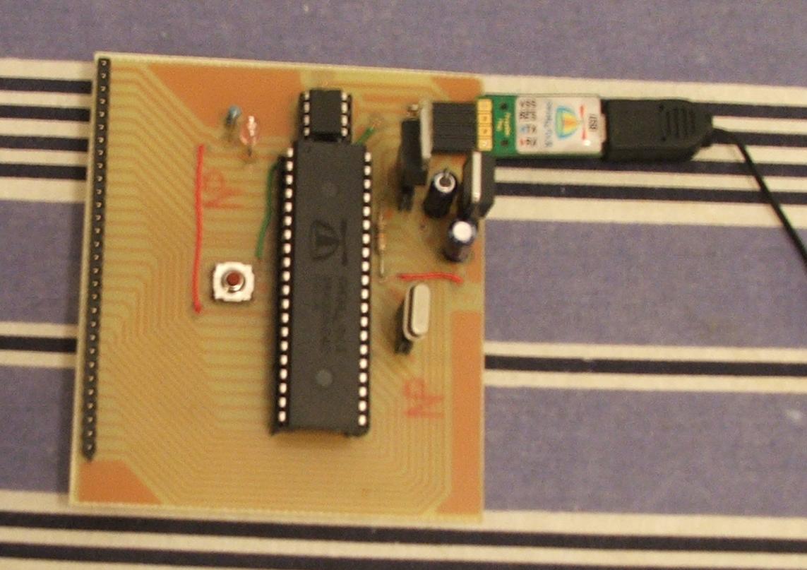
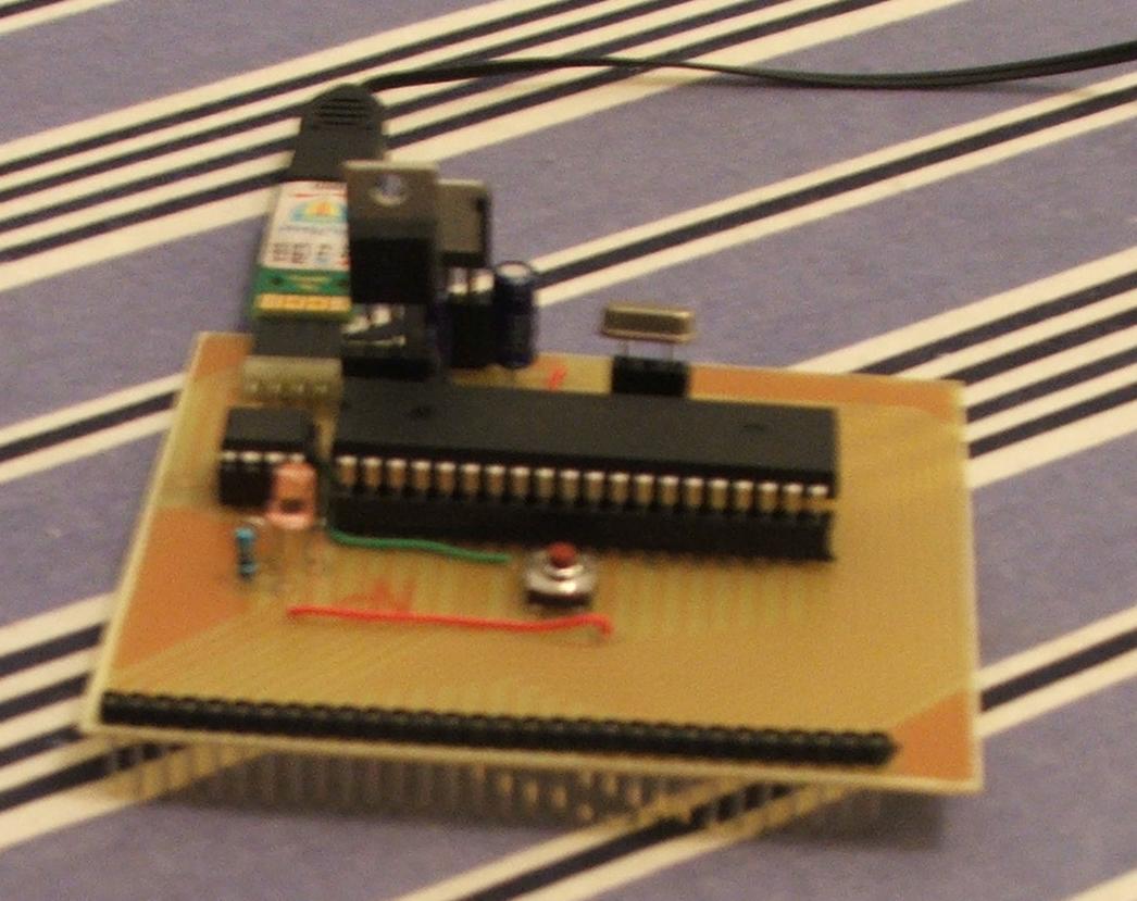
I blow alot of propeller chips because I'm sometimes careless with the 5V. I have the Education kit, so my breadboard is all set up when I blow a chip. All I have to do is drop in a new chip, maybe replace a regulator or two, and presto, good as new. However, I've found that some of the times the reason that I blow the chip in the first place is because the loose wires getting crossed once in a while.

My solution is to make a PCB that is all hard wired and can have all the IO pins out front and ready to plug straight into my breadboard. This allows for easy transition from project to project, too. I'll attach the finished board in a bit, but I'm just curious if anyone would be interested in some of these? I can make these boards at home for around $5, and could ship them via USPS First Class Mail for less than a buck. Anyone interested? Think of it as a protoboard-breadboard hybrid. It's in a nice neat PCB, but all the parts can be easily replaced with little or no soldering.

Post Edited (Philldapill) : 11/30/2008 5:21:40 AM GMT
1143 x 807 - 107K
1046 x 829 - 103K

Comments

  • P!-RoP!-Ro Posts: 1,189
    edited 2008-11-30 04:45
    Sounds great! I recently got myself a protoboard, but already I'm stripping the connections due to de-soldering so often (since I do a crappy job of soldering it in to begin with). With your proposed board, I'm assuming it would be easy to give it a more permanent use as well as being easy to replace parts. Personally, I think it sounds great. So how is this board supposed to look? Will it be on regular boards with the lines going across (like a breadboard), or is it specially made for this purpose?

    ▔▔▔▔▔▔▔▔▔▔▔▔▔▔▔▔▔▔▔▔▔▔▔▔
    PG
  • LeonLeon Posts: 7,620
    edited 2008-11-30 05:07
    This is what I use:

    www.leonheller.com/Propeller/

    Leon

    ▔▔▔▔▔▔▔▔▔▔▔▔▔▔▔▔▔▔▔▔▔▔▔▔
    Amateur radio callsign: G1HSM
    Suzuki SV1000S motorcycle
  • PhilldapillPhilldapill Posts: 1,283
    edited 2008-11-30 05:30
    Alright, I've uploaded a couple of photos of the finished "prototype" prototyping board. I've already found a few changes I'd like to make, but that's the general concept. 28 pins routed out front, plus a 3V and Ground pin. In total, 30 pins, which fits the education kit breadboards perfectly. I'll probably make another version with all 32 pins, plus 3V, 5V, Vin, and a GND pin out front for the larger breadboards. All in all, I'm trying to make a very compact, barebone, board that is easy to replace a part during the expirementing/prototyping phase.

    Oh, btw, this board has pins that connect right into the breadboard, but I may just have female pin headers on the board. With female headers, you would have to connect each pin to the board with a jumper wire, which may be useful sometimes...

    By the way, Leon, I like your board. Simple, and to the point... But how do you connect anything to it? I see the headers in your schematic, but the actual board seems to be lacking them.
  • PhilldapillPhilldapill Posts: 1,283
    edited 2008-11-30 05:37
    Speaking of your board, I saw it has an RCA jack. This may be a little off topic, but I'm thinking about adding an RCA jack on those last 4 pins. I orginally didn't add those pins(P28-P31) because they wouldn't fit on a 30pin breadboard, AND I wasn't sure about using those pins since they are part of the eeprom net. Is it ok to use the TV on these pins?
  • kwinnkwinn Posts: 8,697
    edited 2008-11-30 06:43
    I would be interested in 3 or four if they can be mailed to Canada.
  • Cole LoganCole Logan Posts: 196
    edited 2008-11-30 17:17
    I'd be interested in a couple
  • Oldbitcollector (Jeff)Oldbitcollector (Jeff) Posts: 8,091
    edited 2008-11-30 17:54
    It's a very neat board!

    Would you mind sharing your PCB making process in the Sandbox thread?
    I'd love to hear how you are doing this.

    OBC

    ▔▔▔▔▔▔▔▔▔▔▔▔▔▔▔▔▔▔▔▔▔▔▔▔
    New to the Propeller?

    Getting started with a Propeller Protoboard?
    Check out: Introduction to the Proboard & Propeller Cookbook 1.4
    Updates to the Cookbook are now posted to: Propeller.warrantyvoid.us
    Got an SD card connected? - PropDOS
  • PhilldapillPhilldapill Posts: 1,283
    edited 2008-11-30 20:47
    Sure, OBC! After I got the PCB designed on EAGLE, the whole process from printing out the design, to finished board took about 30 minutes.

    Just FYI to everyone, I'm not sure if I was clear about the board, but the cost I was refering to was just the PCB itself - no components on it. If enough people wanted one of these boards, I suppose I could have the design sent off to a PCB fabricator which would be cheaper. Again, I'd sell it around "at cost".

    Ok, new topic related to this board... It just occured to me that there may be problems with the really long tracks. Pins 0-15 might not be a problem, but pin 28 has the longest path that is parallel to other tracks... about 4 inches. Could this introduce enough stray capacitance or inductance to hinder some higher speed applications? Again, this IS only a prototyping board, not really intended for final projects, but still...
  • LeonLeon Posts: 7,620
    edited 2008-11-30 21:03
    Philldapill said...
    Alright, I've uploaded a couple of photos of the finished "prototype" prototyping board. I've already found a few changes I'd like to make, but that's the general concept. 28 pins routed out front, plus a 3V and Ground pin. In total, 30 pins, which fits the education kit breadboards perfectly. I'll probably make another version with all 32 pins, plus 3V, 5V, Vin, and a GND pin out front for the larger breadboards. All in all, I'm trying to make a very compact, barebone, board that is easy to replace a part during the expirementing/prototyping phase.

    Oh, btw, this board has pins that connect right into the breadboard, but I may just have female pin headers on the board. With female headers, you would have to connect each pin to the board with a jumper wire, which may be useful sometimes...

    By the way, Leon, I like your board. Simple, and to the point... But how do you connect anything to it? I see the headers in your schematic, but the actual board seems to be lacking them.

    They aren't intended for headers. I just run wires from the pads to components on the breadboarding area. I just drill holes as I need them, of course, for additional parts. I could design something similar with headers for circuits on other PCBs, I'm doing that for another chip I'm using.

    Leon

    ▔▔▔▔▔▔▔▔▔▔▔▔▔▔▔▔▔▔▔▔▔▔▔▔
    Amateur radio callsign: G1HSM
    Suzuki SV1000S motorcycle
  • LeonLeon Posts: 7,620
    edited 2008-11-30 21:06
    Philldapill said...
    Speaking of your board, I saw it has an RCA jack. This may be a little off topic, but I'm thinking about adding an RCA jack on those last 4 pins. I orginally didn't add those pins(P28-P31) because they wouldn't fit on a 30pin breadboard, AND I wasn't sure about using those pins since they are part of the eeprom net. Is it ok to use the TV on these pins?

    I use the standard TV output pin group. I think you'll have problems using the EEPROM pins because of the resistors loading the signals.

    Leon

    ▔▔▔▔▔▔▔▔▔▔▔▔▔▔▔▔▔▔▔▔▔▔▔▔
    Amateur radio callsign: G1HSM
    Suzuki SV1000S motorcycle
  • LeonLeon Posts: 7,620
    edited 2008-11-30 21:14
    Philldapill said...
    Sure, OBC! After I got the PCB designed on EAGLE, the whole process from printing out the design, to finished board took about 30 minutes.

    Just FYI to everyone, I'm not sure if I was clear about the board, but the cost I was refering to was just the PCB itself - no components on it. If enough people wanted one of these boards, I suppose I could have the design sent off to a PCB fabricator which would be cheaper. Again, I'd sell it around "at cost".

    Ok, new topic related to this board... It just occured to me that there may be problems with the really long tracks. Pins 0-15 might not be a problem, but pin 28 has the longest path that is parallel to other tracks... about 4 inches. Could this introduce enough stray capacitance or inductance to hinder some higher speed applications? Again, this IS only a prototyping board, not really intended for final projects, but still...

    It shouldn't cause any problems. The maximum speed you can waggle an output is under 10 MHz (I think) and 4" is negligible in terms of a 10 MHz wavelength.

    I was thinking of redesigning my board with a similar track arrangement. I did something similar with a PIC a few weeks ago.

    Leon

    ▔▔▔▔▔▔▔▔▔▔▔▔▔▔▔▔▔▔▔▔▔▔▔▔
    Amateur radio callsign: G1HSM
    Suzuki SV1000S motorcycle
  • PhilldapillPhilldapill Posts: 1,283
    edited 2008-11-30 22:00
    Good to hear, Leon. I was actually thinking more along the lines(no pun intended) of using the Delta-Sigma ADC setup with this board. I've heard that you need the components(cap, resistors, etc.) RIGHT next to the pins.
  • LeonLeon Posts: 7,620
    edited 2008-11-30 22:30
    You will have a problem with that, the connections need to be quite short. You'd be better off putting the parts on your PCB close to the pins.

    Leon

    ▔▔▔▔▔▔▔▔▔▔▔▔▔▔▔▔▔▔▔▔▔▔▔▔
    Amateur radio callsign: G1HSM
    Suzuki SV1000S motorcycle
  • PhilldapillPhilldapill Posts: 1,283
    edited 2008-11-30 23:09
    Ok, thanks Leon. I guess I could still use an external ADC chip, off board. I've got plenty of those anyway.
  • PhilldapillPhilldapill Posts: 1,283
    edited 2008-12-01 22:07
    Alright, here is the modified board. Less connections and a few other changes like a DC power plug, and some holes on the corners for mounting or rubber feet.

    If anyone is interested in one of these when it's done, let me know via private message so we can exchange info. Also, any suggestions, again, let me know as well.
    638 x 766 - 113K
  • LeonLeon Posts: 7,620
    edited 2008-12-01 22:30
    I'd ground all those copper islands, although it will need some wire links.

    Leon

    ▔▔▔▔▔▔▔▔▔▔▔▔▔▔▔▔▔▔▔▔▔▔▔▔
    Amateur radio callsign: G1HSM
    Suzuki SV1000S motorcycle
Sign In or Register to comment.