

Question about lighting and propeller
 gambrino
Posts: 28
gambrino
Posts: 28
Hello forum ,
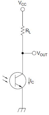
i want to attach to the propeller a phototransistor.I draw the figure 1 in the attachment.The Vout is connected to the propeller . Light input at the base causes the output Vout to decrease from high to low.Can the propeller count the number of ( light off ) ? or i should change the figure?
Thank you in Advance.
Post Edited (gambrino) : 11/29/2008 10:29:59 PM GMT
166 x 385 - 5K
Comments
Hello again, my goal is to count the number light off and throught propeller making some mathematical equations to control another device on the output of the propeller.I connect Vout of the phototransistor to an oscilloscope, when the light is on , the frequency was 50Hz and when was off the frequency was near 0 . Can the propeller count the number of time off ? Do i need the freq. count from the AN001? or i need to convert the analog signal to digital ( first step ). i can't imagine all steps to achieve this goal :-(
the goal is to find something that can surely divide between light ON and OFF.
What do we have as the light is ON? 50 Hz on/off at the IO-PIN
What do we have as the ight is OFF? 0 Hz on/off at the IO-PIN
I think the 50 Hz come from the AC 50 Herz of the light.
If the maximum frequency of the ON/OFF-switching of the light is lower than 10 Hz.
You can use a low-pass-filter.
If the frequency is REALLY low ON/OFF for minimum 10 seconds the most simple "circuit" would be
to connect a capacitor of maybe 1-10 µF parallel to the transistor.
As you have a oscilloscope you can evaluate the right combination of RL and capacity with the oscilloscope
Another way:
Again depending on the ON/OFF-frequency you could poll the IO-PIN by a simple SPIN-program
Light On means 50 Hz ON/OFF. So you check for an OFF-Time bigger than 1/50 = 0,02 seconds
or to make it more reliable OFF-Time bigger than 0,04 seconds
The counters used in ANN001 are for higher and highest frequencies. As these counters are doing start/stop of
counting by hardware.
Now it's up to you to provide some more details about your project and ask more questions
best regards
Stefan
▔▔▔▔▔▔▔▔▔▔▔▔▔▔▔▔▔▔▔▔▔▔▔▔
·"I have always wished that my computer would be as easy to use as my telephone.· My wish has come true.· I no longer know how to use my telephone."
- Bjarne Stroustrup
Post Edited (Ken Peterson) : 12/1/2008 3:58:18 PM GMT
it's like a thought. Knowing the details of your project offers new possabilities to solve the problem:
A common way to detect RPM is to use a little magnet and a hall sensor. This solution would be
completely independent about ambient light or dirt. But the hall-sensor has to be very close to the magnet
1-2 mm.
The software on the prop wpuld be the same as with the phototransistor
best regards
Stefan
Leon
▔▔▔▔▔▔▔▔▔▔▔▔▔▔▔▔▔▔▔▔▔▔▔▔
Amateur radio callsign: G1HSM
Suzuki SV1000S motorcycle
Post Edited (Leon) : 12/1/2008 8:59:36 PM GMT
CON _clkmode = xtal1 + pll16x _xinfreq = 5_000_000 PUB go cognew(@asm, 0 ) DAT org asm movs CTRA, %0 {Monitor pin 0} movi CTRA, %01010_000 {Set CTRa mode to POSEDGE detector} mov frqa, #1 :CountA mov PHSA, 0 {Resets PHSA to 0} waitpne 1, |< 0 {Wait till pin 0 in not High,when light is obscure} mov measure, PHSA {Store PHSA in measure} JMP #:CountA {loop endlessly} measure longis there a special reason why you code in assembler?
The counter is a hardware that works very fast
If you don't need a maximum latency of microseconds
a program in spin will be fast enough.
The value of the counter will be quite accurate as it takes only a few nanoseconds for the
hardwarecounter to switch and capture values.
To make a definite decision about SPIN or PASM: What is the maximum speed in RPM that this motor can have ?
best regards
Stefan
Post Edited (StefanL38) : 12/3/2008 8:25:26 PM GMT