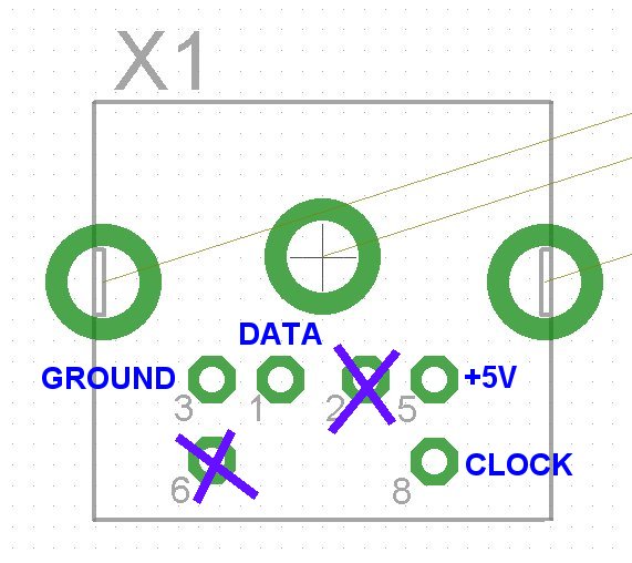
Help to mouse/keyboard pinout
Hi,
I ask·to help the mouse connector, so far I was ever using it in my pcb,
some documents draw in confusion, is this correct pinout, view from above
when we use the cad?
▔▔▔▔▔▔▔▔▔▔▔▔▔▔▔▔▔▔▔▔▔▔▔▔
Fisio
www.elettronicamente.com
www.usb.elettronicamente.com
Open Office file which contains an index of all Propeller Forum


Comments
▔▔▔▔▔▔▔▔▔▔▔▔▔▔▔▔▔▔▔▔▔▔▔▔
Fisio
www.elettronicamente.com
www.usb.elettronicamente.com
Open Office file which contains an index of all Propeller Forum
·
IMHO the Clock line is on pin 6, (not 8) in your picture.
Andy
Pin 2 => +5vdc
Pin 3 => no connection
Pin 4 => Data
Pin 5 => Gnd
Pin 6 => Clock
on your picture 8 should be no connection and 6 should be the clock
I am sure because I measured the voltage with
the multimeter on Propeller demoboard,
also the track towards the VGA connector
confirming whether the +5 V,
I am sure even the pin 3 is (-), because it is·connected to
the ground plane
▔▔▔▔▔▔▔▔▔▔▔▔▔▔▔▔▔▔▔▔▔▔▔▔
Fisio
www.elettronicamente.com
www.usb.elettronicamente.com
Open Office file which contains an index of all Propeller Forum
Post Edited (fisio) : 11/26/2008 10:25:39 PM GMT
en.wikipedia.org/wiki/PS/2_connector
Leon
▔▔▔▔▔▔▔▔▔▔▔▔▔▔▔▔▔▔▔▔▔▔▔▔
Amateur radio callsign: G1HSM
Suzuki SV1000S motorcycle
watching the card created by Chip, visible in this message
NEW PROPELLER DEMO BOARD - picture
and analyzing the figure on page 25 of datasheet version 1.1,
I managed to trace the pin connector seen from top view,
·(when you place the components on CAD)
▔▔▔▔▔▔▔▔▔▔▔▔▔▔▔▔▔▔▔▔▔▔▔▔
Fisio
www.elettronicamente.com
www.usb.elettronicamente.com
Open Office file which contains an index of all Propeller Forum