

frequency reader
 Bobb Fwed
Posts: 1,119
Bobb Fwed
Posts: 1,119
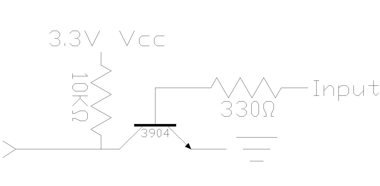
I need to build a simple frequency reader out of the propeller chip (not so I can see the frequency, but so the prop can notify me if the frequencies are too far off). I am working with equipment with a significant amount of interference between components. With our oscilloscopes we can read the equipment frequency with relative ease, and a basic transistor setup *attached*, works until we get more than one piece of equipment running at the same time.
The component we read the frequency off of produces a 3-5V range (with very weak amperage potential), but doesn't ever seem to achieve 0V (earth). The "top" of the curve (not a sine wave) gets very messy with the other pieces of equipment around, so a lower voltage trigger would be nice. The frequency is fairly low 500Hz to 5KHz is all we need, with a resolution or +/-2Hz would be fine.
I'm relatively new to electronic hardware, my emphasis has always been in programming. I'm guessing there may be a solution with an opamp or simply using a high frequency voltage reader.
I am using the propeller and I'd love if it had built in ADC! The trigger I would like is if it would trigger "low" when the minimum input voltage (minV) is achieved, then set "high" when the voltage is at minV + 2V or 1.5V.
But I have no idea how I would even start this.
1521 x 744 - 40K
Comments
An example of a noninverting type is 74HC7014, an example of inverting type is 74HC14.
▔▔▔▔▔▔▔▔▔▔▔▔▔▔▔▔▔▔▔▔▔▔▔▔
Paul Baker
Propeller Applications Engineer
Parallax, Inc.
-Phil
▔▔▔▔▔▔▔▔▔▔▔▔▔▔▔▔▔▔▔▔▔▔▔▔
'Just a few PropSTICK Kit bare PCBs left!
Is there anyway to pull a low voltage lower without affecting the higher voltage (as much)?
By using a resistor network on your input, you can set the "slicing level" almost anywhere you want. The Propeller's digital threshold is Vdd/2, but you can shift this up or down by biasing the input signal using a resistive divider, as shown here:
Resistors R1, R2, and R3 set the bias point. Resistor R4 provides positive feedback for the Schmitt trigger effect. The cap will help to filter out some of the spikes you see on your positive excursions, which will help to make the bias point less critical.
-Phil
▔▔▔▔▔▔▔▔▔▔▔▔▔▔▔▔▔▔▔▔▔▔▔▔
'Just a few PropSTICK Kit bare PCBs left!
  REPEAT
    waitpeq(|< FREQ_IN, |< FREQ_IN, 0)
    OUTA[noparse][[/noparse]SCHMITT]~~
    waitpne(|< FREQ_IN, |< FREQ_IN, 0)
    OUTA[noparse][[/noparse]SCHMITT]~
    freq++
The freq variable is global, which seems to slow it down a bit, but without it I only get about 100Hz higher before it starts petering out. I get up to about 1650Hz without freq, and 1550Hz with. I need to go much higher than this.
▔▔▔▔▔▔▔▔▔▔▔▔▔▔▔▔▔▔▔▔▔▔▔▔
Paul Baker
Propeller Applications Engineer
Parallax, Inc.
As to the Spin code not keeping up, you can use an internal hardware counter to handle the hysteresis feedback and count edges for you. This requires an external inverter, since the counters can only provide negative feedback, not positive. Or you can use PASM (whose reputation for being difficult is largely undeserved, BTW). Which would you prefer?
-Phil
▔▔▔▔▔▔▔▔▔▔▔▔▔▔▔▔▔▔▔▔▔▔▔▔
'Just a few PropSTICK Kit bare PCBs left!
Post Edited (Phil Pilgrim (PhiPi)) : 11/18/2008 7:57:00 PM GMT
CON
   freq_in = 15
   schmitt = 8
'...
VAR
   long freq
'...
PUB go
   cognew(@fcntr, @freq)
   '...

'...
DAT
fcntr   mov frqadr, par
loop    waitpeq fin, fin
        or outa, schm
        waitpne fin, fin
        andn outa, schm
        rdlong ftmp, frqadr
        add ftmp, #1
        wrlong ftmp, frqadr
        jmp #loop

fin    LONG |< freq_in
schm   LONG |< schmitt
frqadr LONG 0
ftmp   LONG 0
Phil is correct that you can run into issues with having two places in code updating the same variable. Let me illustrate this to you, the incrementing of freq is done over two hub access windows. The first hub access is to get the current freq value, the second is to write back the incremented value. Now lets say your other code sets freq to zero in between those two hub accesses. When the assembly code goes to write the incremented variable, it overwrites the 0 with the incremented value which is not what you want because the next time your code goes to read the value it will be be the value accumulated over 2 seconds rather than the 1 second you wanted. You can use the locks to make the operation atomic or·you could use a threshold detector (if·freq is greater than some value) then subtract previous value to get current value, or you could not set freq to 0 and just subtract the·previous freq·value from the current freq value (the most straightforward solution). If you use the last solution you can eliminate the rdlong and the cog's ftmp becomes the "master" copy that the cog continuously updates to hub memory.
He is also correct that·a counter can be adapted for use with this and would not require a seperate cog running assembly.
PS I picked arbitrary values for the pins connected to the frequency in and schmitt, change thier constant value to reflect your setup.
▔▔▔▔▔▔▔▔▔▔▔▔▔▔▔▔▔▔▔▔▔▔▔▔
Paul Baker
Propeller Applications Engineer
Parallax, Inc.
Post Edited (Paul Baker (Parallax)) : 11/18/2008 8:44:52 PM GMT
And, thank you for the PASM code. One of these days I will sit down and force myself to learn PASM.
All frequency counters experience a one-bit "bobble" in their counting. This is because there's no way to predict where in the timing interval the first count and/or last count will occur. One way to minimize this effect is to use a longer timing interval and divide the result by the length of the interval. Another way is to begin your timing interval right at an input edge.
-Phil
▔▔▔▔▔▔▔▔▔▔▔▔▔▔▔▔▔▔▔▔▔▔▔▔
'Just a few PropSTICK Kit bare PCBs left!