Shop OBEX P1 Docs P2 Docs Learn Events
How to use a LED driver? — Parallax Forums

How to use a LED driver?

PromagicPromagic Posts: 17
edited 2008-11-19 05:08 in BASIC Stamp
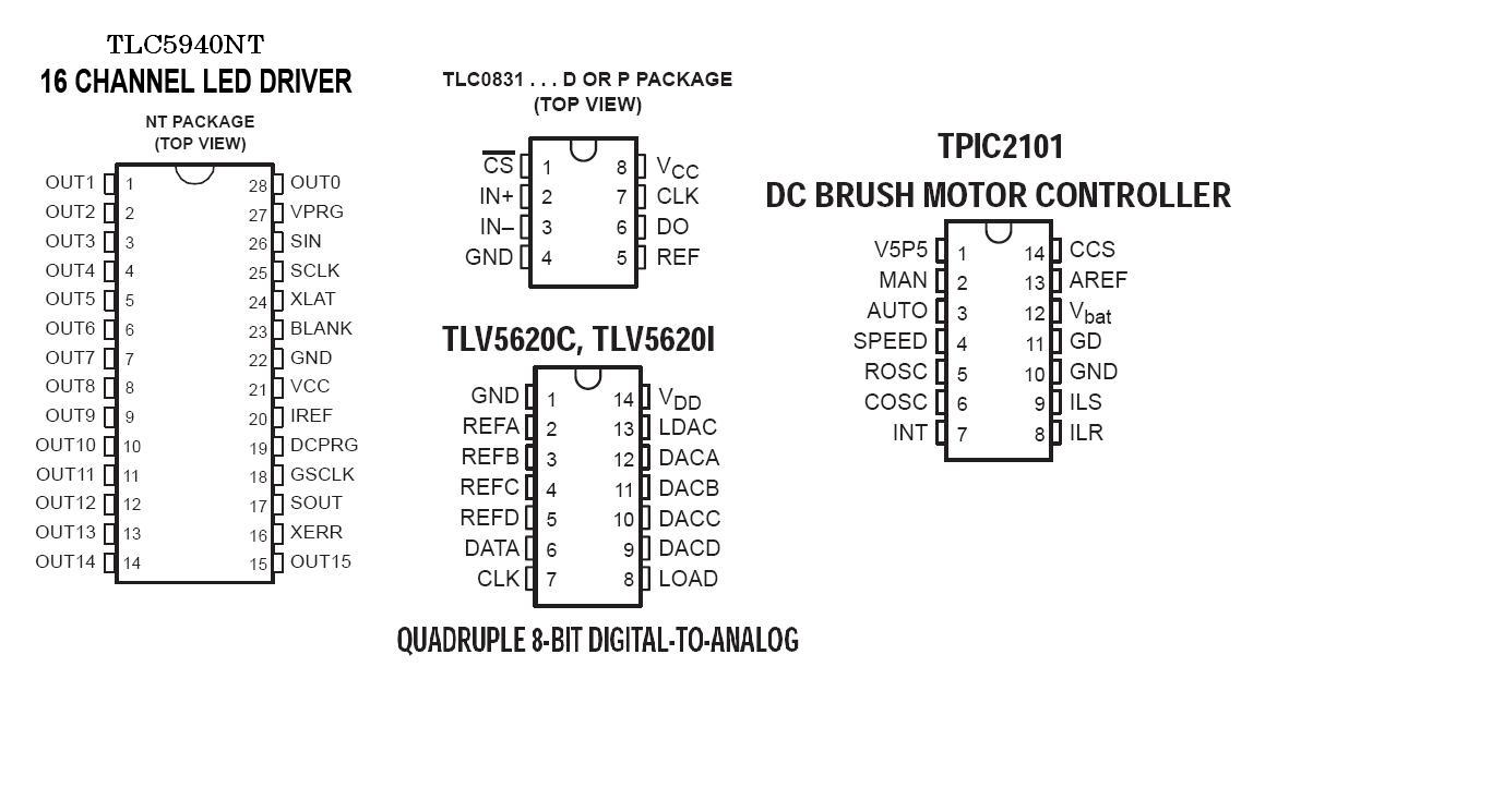
The led driver that i have is the TLC5940 "http://www.ti.com/lit/gpn/tlc5940"

It has 16·channels with pwm,·I have googled for hours now and cant even find a single sample code.
How do I communicate between BS2 and the TLC5940, or ANY LED controller?

Many Thanks!

Comments

  • allanlane5allanlane5 Posts: 3,815
    edited 2008-11-14 13:08
    The data sheet says it needs Serial Data, with a Serial Clock, with 96 bits of data (Divide by 8, == 12 bytes).

    So, on the BS2, you'll need a "SHIFTOUT" command (LSB First, it looks like). Then you'll need to PULSOUT the XLAT signal.

    You'll need to connect a pin for serial_data_out, a pin for serial_clock, a pin for XLAT, and a pin for Ground/Vss.
  • sylvie369sylvie369 Posts: 1,622
    edited 2008-11-14 15:13
    (* Take all of this with a grain of salt - I'm trying to figure these things out myself, and so I'm asking here, not telling *)

    He'll also need a Vdd input, right?
    In addition, it does say "All data are clocked in with the MSB first." on page 12 of the datasheet.
    Also the VPRG pin (pin 27) should be grounded to keep it in GS mode, unless you want to use the Stamp to control the "Dot Correction", in which case you could assign a pin to shift it between those two modes.

    As I understand things, he'll need something like

    Latch  PIN 0   ' Connects to pin 24 of the device
    Sin     PIN 1   ' Connects to pin 25 of the device
    Sclk   PIN 2   ' Connects to pin 26 of the device
    
    
    HIGH Latch
    SHIFTOUT Sin, Sclk, MSBFIRST, [noparse][[/noparse]*some number*\12]
    LOW Latch


    I think that the GS mode is the standard way of putting out data to the output lines, so there are 192 bits (12 bits for each of 16 lines), so that to turn output 0 _only_ to its highest setting, you'd shift out 12 bits of "1" followed by 180 bits of "0". Since the maximum number of bits per shift is 16, this will have to be done with multiple values. From the Stamp Manual, p. 437:
    Stamp Manual said...
    Some devices require more than 16 bits. To solve this, you can use a single
    SHIFTOUT command with multiple values. Each value can be assigned a
    particular number of bits with the Bits argument. As in:
    SHIFTOUT 0, 1, MSBFIRST, [noparse][[/noparse]250\4, 1045\16]
    The above code will first shift out four bits of the number 250 (%1010) and
    then 16 bits of the number 1045 (%0000010000010101). The two values
    together make up a 20 bit value.

    So the SHIFTOUT command to turn on just output zero might be

    SHIFTOUT Sin, Sclk, MSBFIRST, [noparse][[/noparse]4096\12, 0\12, 0\12, 0\12, 0\12, 0\12, 0\12, 0\12, 0\12, 0\12, 0\12, 0\12, 0\12, 0\12, 0\12, 0\12]


    I'll bet that even if that works, it's the least elegant way to do it, but am I in the ballpark here?

    Then each of the outputs can be set to a brightness anywhere from 0 to 4096, so something like this would give him full output on output 0, and each following output be half as strong (with the last three off entirely):

    SHIFTOUT Sin, Sclk, MSBFIRST, [noparse][[/noparse]4096\12, 2048\12, 1024\12, 512\12, 256\12, 128\12, 64\12, 32\12, 16\12, 8\12, 4\12, 2\12, 1\12, 0\12, 0\12, 0\12]
    

    Post Edited (sylvie369) : 11/14/2008 3:21:57 PM GMT
  • LilDiLilDi Posts: 229
    edited 2008-11-15 20:27
    The most difficult part of the TLC5940 is generating the 4096 GSCLK pulses and after every 4096 GSCLK pulse, generating the BLANK pulse. Also, if you ground the DCPROG and VPROG pins, the internal pre-programmed EEPROM dot correction data is used so you don't need to serially clock in any dot correction data. The TLC5940 is shipped with the EEPROM dot correction set at 100% which is just fine for most applications. I used a separate PICAXE 8M MPU to generate the GSCLK and BLANK pulses. Its an 8 pin BASIC MPU that cost about a buck and a half. It spares you a lot of programming headaches on the BS2. I wrote code a while back, but can't find it to post here. If I find the code I will post, but basically you would use the SHIFTOUT command as mentioned in the previous posts to this thread to clock in 192 bits, MSB first, then pulse XLAT to load the 192 bits into the TLC5940. XLAT should be pulsed when BLANK is pulsed high.
  • PromagicPromagic Posts: 17
    edited 2008-11-19 05:08
    Ok!·I have found some new leads! idea.gif
    First of all is something called a "serial-in parallel out shift register", Does anyone know how to program one?
    http://focus.ti.com/docs/prod/folders/print/cd54act164.html
    http://www.cs.cmu.edu/~RAS/Docs/surface/shift_register.html·-This was helpfull

    Second, Is the Good old fashioned way! Fancy Wiring!
    3 ports = 6 Leds
    4 ports = 12 Leds
    5 ports = 20 Leds
    6 ports = 30 Leds
    8 ports = 56 Leds

    Each individually controllable!
    http://www.josepino.com/pic_projects/?how_control_leds.jpc

    ▔▔▔▔▔▔▔▔▔▔▔▔▔▔▔▔▔▔▔▔▔▔▔▔
    ···· -Devin


    "I can only ask every question once."

    Post Edited (Promagic) : 11/19/2008 5:31:43 AM GMT
    1024 x 661 - 88K
Sign In or Register to comment.