

Interface
 Davidicus
Posts: 20
Davidicus
Posts: 20
Hello,
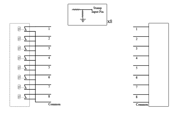
I want to use the Stamp as a Data Logger for a piece of equipment that uses 8 contact closures to reveal its internal state (shown on the left side of the schematic). I've configured 8 input pins on the stamp using resistors (as shown in the center portion of the schematic). I hooked up the Stamp to the piece of equipment and it works perfectly. The problem I have is that the equipment needs to reveal its internal state to another piece of hardware that connects to it (shown on the right side of the schematic).
I need to buffer the Stamps inputs from the equipment on the right. I tried to use DPDT relays but the back voltage was too great and caused the equipment to malfunction. I'm hoping to be able to use something non-mechanical (Transistors, solid state relay, etc) but I do not know enough about how to configure the circuit.
Any help would be greatly appreciated!!
Thanks, Dave
600 x 400 - 67K
Comments
The schematic is not quite enough information to know how to connect the 2 pieces of equipment and the Stamp. You show the contacts on the left side but you will need to know the characteristics of the other unit. It is common for an input to expect a pullup when not active and to be pulled low when active. That seems to match the functionality from the left. Your Stamp interface uses a pull down. It may be as easy as reversing that but more details would be needed to be sure.
I updated the schematic to show what I would like to do. I believe I need to electrically separate the stamp from the right-hand equipment so that they do not interfere (i.e.-short, voltage problems, etc.) with each other.
DAve
When you know what voltage appears at each of the eight terminals in each of its two possible conditions, it will be trivial to devise a way to present these two conditions to the inputs of a Stamp. Until you know that, you cannot devise a way.
▔▔▔▔▔▔▔▔▔▔▔▔▔▔▔▔▔▔▔▔▔▔▔▔
· -- Carl, nn5i
I appreciate the help.
Dave
You show the "common" lead of your two ultra-mysterious devices connected to the +Vdd of the Stamp, the positive supply. If your measurements show that the voltages at the eight pins of your right-side device swing negative from common, this would be correct. But if they swing positive from that common -- much more likely -- you'd want to connect that common to Vss, the negative. Either way, it's not going to affect your two devices at all, though getting it wrong might fry your Stamp.
▔▔▔▔▔▔▔▔▔▔▔▔▔▔▔▔▔▔▔▔▔▔▔▔
· -- Carl, nn5i
I was able to measure the voltage and it was right around 8 volts. I know Ohms law to get the values of the resistors, but I do not know the current that will be applied to the stamp Input pins because the right-hand equipment will be using some of the current (but I don't know how much).
I'm thinking that I should base my calculations as if the stamp used all of the current in the circuit since this will only make the resistor values more conservative. Does this sound like the right way to go?
Dave
If you base your calculations "as if the stamp used all of the current in the circuit" that will be the wrongest you can possibly get, since it will actually use none. None at all. NONE!
▔▔▔▔▔▔▔▔▔▔▔▔▔▔▔▔▔▔▔▔▔▔▔▔
· -- Carl, nn5i
Carl, I appreciate your input and help. I do have a question, though. The Stamp Handbook says, "General-purpose I/O pins: each can source and sink 30 mA." I thought this meant that I needed to limit the current going to the IO pin using a resistor. If the IO pin was like an open circuit, no resistor would be necessary. I think that it is the resistor that causes the pin to act very much like an open circuit as it limits the current going to the pin to 20-30 mA.
The simplified circuit makes things much easier as it only requires calculation of the value of one resistor. Using Ohm's Law, I get 8/.02 = 400 Ohms. This will limit the current to 20 mA.
I don't claim that this is correct. This is only according to my limited knowledge.
Can anyone confirm this for me?
Dave
So, this is how the INPUT statement works, simply, the basic stamp essentially becomes an open circuit on the line. Line a voltage meter the stamps internal resistance raises to well over a million ohms. So there is basically no current. However, in reality there is some current...but you would need to know the internal resistance of the stamp to calculate the voltage drop needed across the external resistor as to not damage the stamp.
Just replace your resistor with a 10k or something resistor to ensure that the current can never get to high. Since there is basically no voltage drop the stamp will see the 0v or 8v potential so you have nothing to worry about.
Your current design is also fine. However, not as safe as one with a larger resistance.
▔▔▔▔▔▔▔▔▔▔▔▔▔▔▔▔▔▔▔▔▔▔▔▔
Nyamekye,
▔▔▔▔▔▔▔▔▔▔▔▔▔▔▔▔▔▔▔▔▔▔▔▔
· -- Carl, nn5i
Thank you, Thank you, Thank you. I appreciate the help.
The reason is, yes, the BS2 input pin, when set as an input, is a high-impedance, UNTIL the input voltage goes below -0.6 volts, or above 5.6 volts. When that happens two 'protection diodes' begin conducting to protect the rest of the chip.
The effect of this is to 'clip' the signal the BS2 sees to 0 to 5 volts. BUT, when this "clipping" happens, you MUST have a 22 Kohm resistor in-series to drop the current those "clipping" diodes see -- they're pretty small, and they burn out easily.
Now, if you're reading either an 'open circuit' or 'closed circuit', then you DO also need a 'pull-up' or 'pull-down' resistor to give your input pin a signal. Otherwise, an open input pin connected to nothing is technically an "antenna", and will pick up random noise (typically 60 Hz line noise). So you really can't "forget" about either resistor on your input pins -- you need both of them.
On the other hand, with those series resistors in place your pull-ups (or pull-downs), if you need them at all,·would have to be quite large values -- else the mystery boxes could not overcome them when working through a 22K or 100K resistor.· You really need to know the voltages at those pins in BOTH states, and you mention measuring only one state (8 volts).· If those lines swing between two voltages (as surely they must) when the two Iron Curtain Enigmas talk to each other, then you won't need pull-ups or pull-downs.
▔▔▔▔▔▔▔▔▔▔▔▔▔▔▔▔▔▔▔▔▔▔▔▔
· -- Carl, nn5i
If I replaced the 400 Ohm resistor with a 100K, would that make the circuit work?
My one remaining concern is that the circuit as shown seems to 'short' 8 volts to ground. That will only work if the 8-volt signal has some resistance in the line -- I'm assuming there must be some to the right of the box, as none is shown to the left of the box.
So, if internally to the box, it has some 'pull-up' resistor to +8 volts, then yes the BS2 (with the 100K in-series resistor) should read that as a "one", and you don't need an additional pull-up resistor near the BS2.
Thanks for your help Kye, allan and Carl.