

First time surface mount soldering (SPI serial FRAM)
 RDL2004
Posts: 2,554
RDL2004
Posts: 2,554
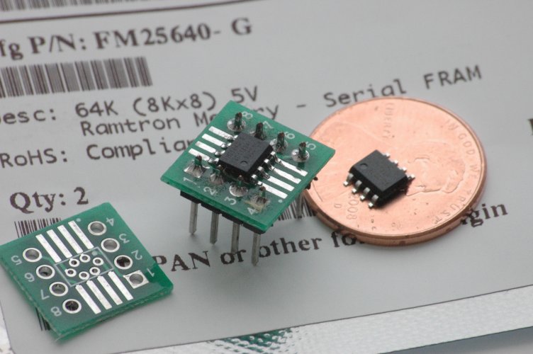
I got this strange urge to play with one of those FRAM chips, but they're only available in surface mount. So, I soldered my first surface mount chip the other day and it didn't turn out too bad [noparse]:)[/noparse]

I used the "blob of solder, followed by flux and Solder Wick" method (Solder Wick is amazing). I used a spring clamp to hold the chip in place. Next time I'm going to try gluing it first, because this one is a little mis-aligned.
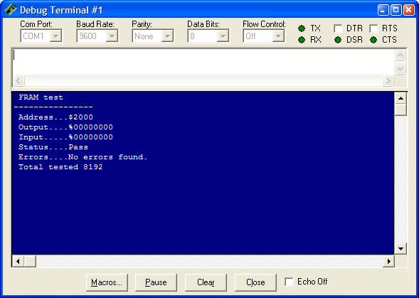
I got the test code working last night and it seems the chip survived okay.

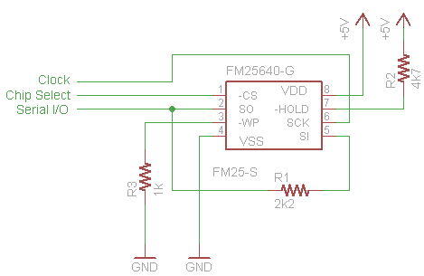
Here is the basic schematic I used for the testing circuit. The code is attached.

▔▔▔▔▔▔▔▔▔▔▔▔▔▔▔▔▔▔▔▔▔▔▔▔
- Rick
Post Edited (RDL2004) : 11/2/2008 5:04:29 PM GMT
I used the "blob of solder, followed by flux and Solder Wick" method (Solder Wick is amazing). I used a spring clamp to hold the chip in place. Next time I'm going to try gluing it first, because this one is a little mis-aligned.
I got the test code working last night and it seems the chip survived okay.
Here is the basic schematic I used for the testing circuit. The code is attached.
▔▔▔▔▔▔▔▔▔▔▔▔▔▔▔▔▔▔▔▔▔▔▔▔
- Rick
Post Edited (RDL2004) : 11/2/2008 5:04:29 PM GMT
752 x 500 - 57K
589 x 419 - 15K
469 x 305 - 4K

Comments
because now, when Serial I/O is driven high(low) while SO is driven low(high),
there is a very low resistance path (eg. short circuit) between Serial I/O and SO.
regards peter
In first place I used a socket to use it as an 'adapter'. I soldered each chip pin to a socket pin with a thin piece of wire. It did not work! Despite my tester shown all connections were Ok.
Then I soldered another FRAM chip to a breakuout board (like the one in your pictures). I used only flux and an ordinary iron. This time the FRAM did work!
Also, I thought R1 was to prevent any possibility of a short between SI and SO, I don't see how connecting to SI would be any better. Should I use a larger resistor? I have run the chip through my test program over a dozen times with no problems.
▔▔▔▔▔▔▔▔▔▔▔▔▔▔▔▔▔▔▔▔▔▔▔▔
- Rick
But suppose you were to make a program error where Serial I/O would be high
while SO was low, that generates a short. By connecting Serial I/O to SI
resistor R1 serves as current limiter between Serial I/O and SO.
regards peter
I am clueless.
Thanks,
Bill
www.sparkfun.com/commerce/product_info.php?products_id=494
OBC
▔▔▔▔▔▔▔▔▔▔▔▔▔▔▔▔▔▔▔▔▔▔▔▔
New to the Propeller?
Getting started with a Propeller Protoboard?
Check out: Introduction to the Proboard & Propeller Cookbook 1.4
Updates to the Cookbook are now posted to: Propeller.warrantyvoid.us
Got an SD card connected? - PropDOS
▔▔▔▔▔▔▔▔▔▔▔▔▔▔▔▔▔▔▔▔▔▔▔▔
- Rick