

ADC
 Promagic
Posts: 17
Promagic
Posts: 17
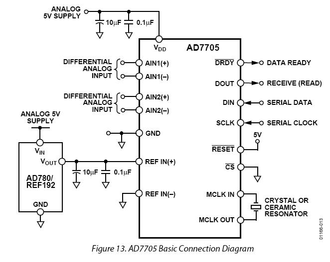
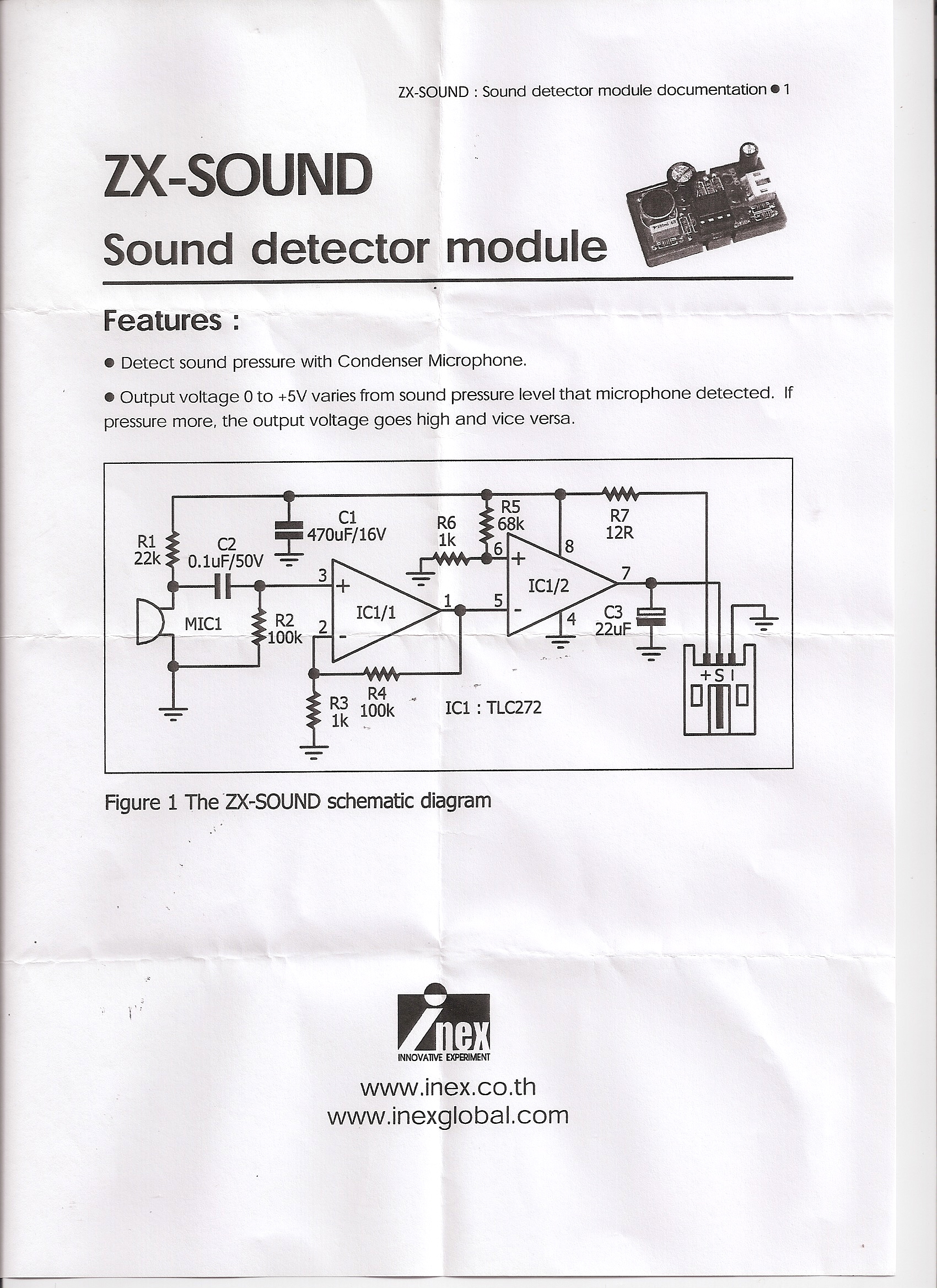
I am trying to read the 0-5v reading from a Sound sensor·I bought. I have a AD7705 ADC from Analog Devices. My problem is that·I don't understand what pins·go where.
I realise VSS is power and GND is ground, but which one do I plug in the input and which one does·the output come from?
http://www.analog.com/en/analog-to-digital-converters/ad-converters/ad7705/products/product.html· - Page
http://www.analog.com/static/imported-files/data_sheets/AD7705_7706.pdf·· - Data Sheet
Many Thanks!
662 x 527 - 44K
1700 x 2338 - 1M
Comments
I looked at the " ADC.jpg " Image You Attach. The "scan0001.jpg" Image download keeps hanging up part way in the download, so I couldn't see what was in the D.L. But I might be of some help w/ the pin use... ? does Your code use SHIFTIN/SHIFTOUT???. or some other COM. method????...maybe I2C????
_______________________________________________$WMc%__________________in________________
Post Edited ($WMc%) : 11/2/2008 7:48:26 PM GMT
Typical setup for a AD7705:
'
AD7705 Constants
WriteCLK CON %00100000 'Next operation a write to the Clock Register
ReadClk CON %00101000 'Next operation a read from the Clock Register
ClockSET CON %00001100 'Clock Register Datasheet P19
WriteSTP CON %00010000 'Next operation a write to the Setup Register
ReadSTP CON %00011000 'Next operation a read from the Setup Register
SetupSET CON %01111010 'Setup Register Datasheet P17
WriteDRDY CON %00001000 'Read Communications Register to determine status DRDY bit
WriteDATA CON %00111000 'Next Operation a Read from the DATA Register.
ZeroCal CON %10110010 'Zero Calibration
SerReset CON %11111111 'Value for Serial Interface reset
'Initialize the Rain/Snow Gage ADC
'1. WRITE TO COMMUNICATIONS REGISTER SELECTING CHANNEL & SETTING
' UP NEXT OPERATION TO BE A WRITE TO THE CLOCK REGISTER (20 HEX)
SHIFTOUT RS_Din,RS_CLK,MSBFIRST,[noparse][[/noparse]WriteCLK]
'2. WRITE TO CLOCK REGISTER SETTING THE CLOCK BITS IN ACCORDANCE
' WITH THE APPLIED MASTER CLOCK SIGNAL AND SELECT UPDATE RATE FOR
' SELECTED CHANNEL (0C HEX)
SHIFTOUT RS_Din,RS_CLK,MSBFIRST,[noparse][[/noparse]ClockSET]
PAUSE 200
SHIFTOUT RS_Din,RS_CLK,MSBFIRST,[noparse][[/noparse]READCLK]
SHIFTIN RS_Dout,RS_CLK,MSBPOST,[noparse][[/noparse]rs_config]
'3. WRITE TO COMMUNICATIONS REGISTER SELECTING CHANNEL &
' SETTING UP NEXT OPERATION TO BE A WRITE TO THE SETUP REGISTER (10 HEX)
SHIFTOUT RS_Din,RS_CLK,MSBFIRST,[noparse][[/noparse]WriteSTP]
PAUSE 200
'4. WRITE TO SETUP REGISTER CLEARING F SYNC, SETTING UP GAIN,
' OPERATING CONDITIONS & INITIATING A SELF-CALIBRATION
' ON SELECTED CHANNEL (40 HEX)
SHIFTOUT RS_Din,RS_CLK,MSBFIRST,[noparse][[/noparse]SetupSET]
PAUSE 200
GOSUB WaitForADC
RETURN
Wow the ADC0831 and the LTC1298 is MUCH simpler!
Thank you very much!!