

Two-component Video DAC
 Phil Pilgrim (PhiPi)
Posts: 23,514
Phil Pilgrim (PhiPi)
Posts: 23,514
The video DAC circuit that I prefer to the standard Parallax circuit is the following:

Both circuits provide a 1V p-p baseband signal into a 75-ohm load. But the Parallax circuit has a baseband source impedance of 156.2 ohms. This one's source impedance is 74.8 ohms, a better match for long cable runs.
I was laying out a small board that was getting quite cramped — too cramped for my favorite video DAC. So I started looking for alternatives that use fewer parts and came up with the following:

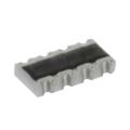
Basically, this just replaces the 191-ohm resistor to ground with a 215-ohm resistor, which is pretty close. The two components are both 430-ohm x 4 resistor arrays, like the one pictured here:

They're nearly as cheap as single resistors and count as only two components for pick-and-place assembly purposes. Plus, together they count as a single line item in the bill-of-materials — a double advantage.
Since the resistor to ground is not ideal, the impedance changes to 78.2 ohms and the DAC sources 1.05V p-p into a 75-ohm load. Measured on the scope, however, the p-p voltage was more like 1.01V, which is plenty close.
-Phil
▔▔▔▔▔▔▔▔▔▔▔▔▔▔▔▔▔▔▔▔▔▔▔▔
'Just a few PropSTICK Kit bare PCBs left!
Post Edited (Phil Pilgrim (PhiPi)) : 10/28/2008 2:57:00 AM GMT
Both circuits provide a 1V p-p baseband signal into a 75-ohm load. But the Parallax circuit has a baseband source impedance of 156.2 ohms. This one's source impedance is 74.8 ohms, a better match for long cable runs.
I was laying out a small board that was getting quite cramped — too cramped for my favorite video DAC. So I started looking for alternatives that use fewer parts and came up with the following:
Basically, this just replaces the 191-ohm resistor to ground with a 215-ohm resistor, which is pretty close. The two components are both 430-ohm x 4 resistor arrays, like the one pictured here:
They're nearly as cheap as single resistors and count as only two components for pick-and-place assembly purposes. Plus, together they count as a single line item in the bill-of-materials — a double advantage.
Since the resistor to ground is not ideal, the impedance changes to 78.2 ohms and the DAC sources 1.05V p-p into a 75-ohm load. Measured on the scope, however, the p-p voltage was more like 1.01V, which is plenty close.
-Phil
▔▔▔▔▔▔▔▔▔▔▔▔▔▔▔▔▔▔▔▔▔▔▔▔
'Just a few PropSTICK Kit bare PCBs left!
Post Edited (Phil Pilgrim (PhiPi)) : 10/28/2008 2:57:00 AM GMT
Comments
I presume all else (software, etc.) is the same, including the optional use of the audio???
Happy Holidays,
Mark
-Phil
▔▔▔▔▔▔▔▔▔▔▔▔▔▔▔▔▔▔▔▔▔▔▔▔
'Just a few PropSTICK Kit bare PCBs left!
How is source impedance calculated here?
You could think of the one to ground as also going to a Prop pin that is outputting 0...
That was my initial idea. But that calculates as about 64 Ohm, not 75.
-Phil
Wouldn't it be better to use the 4th pin for more colors with regular composite?
I've experimented with the audio subcarrier over RF with that pin, and it works. But I doubt many people ever use it for that. I've also used it with a DUTY-mode counter to produce a 16-level grayscale overlay (for the PropCAM) atop the regular video. That works if you add a 330 pF cap to ground as a low-pass filter. Using it to create extra hues would be tough, though, since it would have to be synced to the chroma x16 master clock, which is not program-accessible.
-Phil
Once that's done, BTW, artifacts can also be used on NTSC, to generate a lot more colors. I personally have not written that code as there is no place to actually store the color data. The nice, fast external RAM looks intriguing though... Need to buy one of those.
I propose some possible alternate uses:
* If the resistor has an alternate hole, then from prop pin, a series resistor R1, 0.1" cap to ground (C2) or +V (C1) [3 holes, center common] and 0.1" cap (C3) to another output [connector]. [see diagram]
1. 1pin TV (mono) for debugging: R1 = any value 100R-1K1, C1=nc, C2 optional ~180-220R or nc (better impedance matching), C3 = link
2. Audio (mono) out: R1, C2 (need to check values), C3 = ~4,7uf electro, C1 = nc
3. 1pin Kbd R1 = ~100R (think up to 1K1 would be fine), C1 = 10K, C2 = nc, C3 = link, output to SD of PS2 keyboard (also requires 10K from SC to +3V3 or +5V on keyboard connector)
But, I doubt anybody uses that either.
Problem is that the 4th pin is written into the drivers, so I guess we're stuck with it.
I'll have to check out ericball's driver...
That 4th pin is also S-video chroma output, which currently isn't used much either, though some of my stuff will have that option in the future.
Just FYI, that's all. I only wanted to highlight that it's not all about broadcast.
-Phil