

PCF8574 circuit question
 T Chap
Posts: 4,260
T Chap
Posts: 4,260
I may have done something backwards. First time using an expander as input, the documents say regarding the 8575 and 8574 that they are to be written high before being used as inputs. However writing them high, means they have 3.3 volts sitting on the pins at time of read, so this is really confusing. Whatever you write, is what you read. The only difference being if you force the pin to a lower or higher state than it was written to, so why no damage forcing the high to a low, or low to a high?
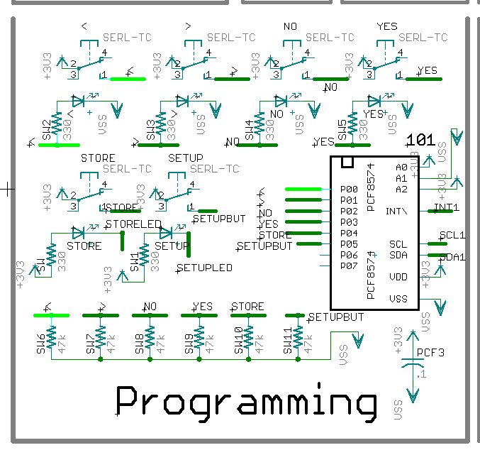
In the circuit below, I set the inputs to be pulled low with a 47k on each pin. When all pins are written high as instructed, the pins read over 1.5v.
Here are the I2C steps:
Start
Send address, write state + 0
Write all pins high %1111_1111
Send address, read state + 1
testbyte := i2c.i2cread(address, 1)
Stop
This produces %1111_1111 on read regardless of the buttons state, as it is seeing a voltage above it's threshold based on being written high previously, the 47k pull downs are not enough to drop it below the trigger level.
So I am now considering cutting some traces and reversing things, so the buttons pull down, and the resistor pulls up instead, reverse logic at the inputs.
It would be much simpler to replace the 6 req'd pull down's with a stronger pull, hopefully to get the voltage down below the trigger point.
I really don't get this concept of putting a high on pins you intend to read, I suppose it is just a compromise to allow it to both read and write.
Which way do I go to solve this guys?
Thanks
677 x 641 - 89K
Comments
The I/O pin structure uses a weak pullup with a "booster" that provides a stronger pullup for a short time, then turns off.· After the I/O pin is written with a·1, the weak pullup remains in operation, but can easily be pulled down with any logic output or switch.· The weak pullup usually uses a current source, a circuit that supplies a specific maximum amount of current (often 150uA or something similar).
It was too much hassle to redo the schematic to put pullups on the pins, so I simply put 10k's where the 47k's were, which solved the problem with the inputs sitting above the trigger threshold.