High frequency noise from DC-DC Step up!
Hello All,
Im working on a GPS project that uses a single cell LIPO (so 3.0-4.2v range) and a 5v LCD - so am using a MAX856 DC-DC Step up IC.
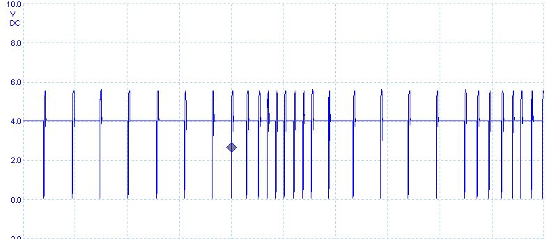
From the IC I get slightly higher than 5v - about 5.4v - and a high frequency noise - the LCD works ok though which is good!
On the picoScope·:-)·(www.picotech.com) I get the attached waveform.· Something is not right!
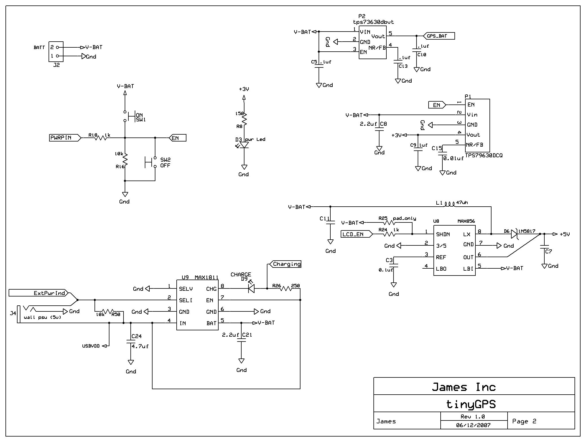
I've also attached the relevant part of the circuit· Currently the SHDN pin is held HIGH, C11 is 30uf, C7 is 20uf·and L1 is a 22UH axial Inductor.
Thanks for any help!
James
PS - also attached the MAX856 datasheet.


Comments
▔▔▔▔▔▔▔▔▔▔▔▔▔▔▔▔▔▔▔▔▔▔▔▔
Paul Baker
Propeller Applications Engineer
Parallax, Inc.
J
James
Edit: Are you using an inductor designed for power switching ? Some inductors, especially the ones that look like resistors "Drosselspule" have very small cores not suitable for almost anything like this.
Thanks for the reply! The Inductor is this one - http://uk.farnell.com/516533/passives/product.us0?sku=epcos-b82144a2223k&_requestid=465419
So maybe not - the product page text says:
INDUCTOR, AXIAL, 22UH
Inductor type:High Frequency / RF
Inductance:22µH
Tolerance, inductance:±10%
Resistance:0.35ohm
Current, DC max:1100mA
Frequency, resonant:12MHz
Case style:Axial
Q factor:50
Material, core:Ferrite
Tolerance, +:10%
Tolerance, -:10%
Climatic category:55/125/56
Diameter, body:5.2mm
Diameter, lead:0.63mm
Frequency, Q factor:2.52MHz
Frequency, inductance measurement:0.1MHz
I was thinking of the capacitance though - as my board has a design fault for that - i.e. the spec says 68uf and I have 30uf!! I'll probably add more!
James
Something like that:
http://uk.farnell.com/7429878/passives/product.us0?sku=epcos-b82462a4473k
And fix the capacitor problem
Have fun
As mentioned the inductor you had is definitely not suitable as it even if the inductance is somewhere in the correct range it does not have the "storage" that a larger core has and so it saturates. A plastic food bag may hold a litre of water but it won't hold a litre of wet cement (that argument should hold water).
However, your signals show the output going to 0V which seems highly improbably as the 1N5817 schottky diode and output capacitor will prevent that from happening. I hope C7 is the right value and that you have actually wired this circuit the way it is drawn. The 4V steady level you are seeing is probably the battery voltage less a few hundred millivolts drop through the diode. So I get the feeling that you have taken the signal from before the diode rather than after and this is exactly what you would see.
*Peter*
Thinking about it my prototype was on a parallax carrier board - so would have had a large(er) decoupler on the linear voltage reg output. So definatly one to fix - cause I didn't have this problem then.
I shall look for an axial/radial package power inductor too.
James