Shop OBEX P1 Docs P2 Docs Learn Events
Propeller™ P8X32A Datasheet Missing something ? — Parallax Forums

Propeller™ P8X32A Datasheet Missing something ?

grasshoppergrasshopper Posts: 438
edited 2008-10-04 18:10 in Propeller 1
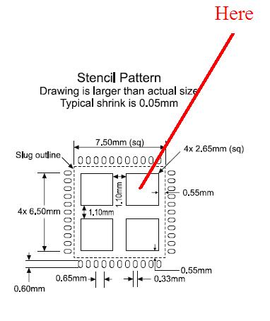
I am designing a circuit board and looking through the Propeller™ Data sheet I cant find any information that explains what the 4 square plugs are for on the 44-Pin QFN Chip. I called parallax tech-support but the gentleman stated "it was ground and was mentioned in the data sheet." Any ideas if this is correct? Picture is attached
382 x 454 - 24K

Comments

  • DufferDuffer Posts: 374
    edited 2008-10-03 21:11
    Grasshopper,

    Check out the following thread in the Sandbox section http://forums.parallax.com/showthread.php?p=755575·There are several comments regarding the requirements for mounting QFN chips.

    Duffer
  • Paul BakerPaul Baker Posts: 6,351
    edited 2008-10-03 21:14
    Yes the QFN package has an exposed metal slug underneath the chip, it is a single square covering about 90% of the package area, the dotted line in the stencil diagram shows it's outline. This pad needs to be soldered onto a corresponding·pad on the PCB which is grounded.·The QFN package is intended for use in reflow processes. In a reflow process solder paste is applied to the board using a stencil, the stencil cut outs determine where solder paste is applied to the board. After the paste has set (becomes·a little more viscous and·tacky) the components are populated and the board is sent through a reflow oven to solder the components on the board.

    The picture you have shown is the recommended stencil pattern to use with the QFN package. The reason there are·multiple aperatures for the exposed slug is that it is a large surface area and filling the entire space would deposit too much paste for the slug which causes improper alignment and bridging between the slug and pins. The spacing between the aperatures allows·the excess solder paste to wick into the voids·and not migrate out to the pins where a short would cause a faulty soldering job.

    In general, if you are not using a reflow process on your boards you should use the QFP package.

    ▔▔▔▔▔▔▔▔▔▔▔▔▔▔▔▔▔▔▔▔▔▔▔▔
    Paul Baker
    Propeller Applications Engineer

    Parallax, Inc.

    Post Edited (Paul Baker (Parallax)) : 10/3/2008 9:31:37 PM GMT
  • Phil Pilgrim (PhiPi)Phil Pilgrim (PhiPi) Posts: 23,514
    edited 2008-10-03 21:34
    Paul,

    Given that the Propeller is not a power hog, so doesn't dissipate much heat, that the QFP package needs no additional cooling, and that the QFN package has just as many Vss connections on its periphery, why is the bottom slug on the QFN package even necessary? Was it to avoid a custom QFN package design? Or is there more to it than that?

    -Phil

    ▔▔▔▔▔▔▔▔▔▔▔▔▔▔▔▔▔▔▔▔▔▔▔▔
    'Still some PropSTICK Kit bare PCBs left!
  • grasshoppergrasshopper Posts: 438
    edited 2008-10-03 21:35
    Thanks for the information. I am intending on using the re-flow process (want to sell thousands) just was not sure on the IC foot print. Again thanks for the quick response.
  • Paul BakerPaul Baker Posts: 6,351
    edited 2008-10-03 21:41
    Phil, I don't know the particulars, but I would imagine that it was the standard package availible from the comany we use. Frequently using a custom package raises the cost so much that it isn't possible to sell it at a cost effective price. The SX52 is a prime example of this. Another factor to consider is that with QFP packages not having any legs the mechanical bonding to the board is much less than with the equivalent QFP. This makes the board susceptable to damage from vibrations and mechanical stressing of the board by prying off some of the contacts. With the ground slug soldered to the board the risk of this is greatly diminished.

    ▔▔▔▔▔▔▔▔▔▔▔▔▔▔▔▔▔▔▔▔▔▔▔▔
    Paul Baker
    Propeller Applications Engineer

    Parallax, Inc.
  • Phil Pilgrim (PhiPi)Phil Pilgrim (PhiPi) Posts: 23,514
    edited 2008-10-03 22:07
    Thanks Paul: that makes sense. I hadn't thought about the bonding issue, which might also be exacerbated by the QFN pins not being able to flex like those on the QFP. With different thermal expansion coefficients, the chip and board might sooner part company without the additional reinforcement.

    -Phil

    ▔▔▔▔▔▔▔▔▔▔▔▔▔▔▔▔▔▔▔▔▔▔▔▔
    'Still some PropSTICK Kit bare PCBs left!
  • LeonLeon Posts: 7,620
    edited 2008-10-03 22:10
    BGA chips can have problems with thermal expansion and boards flexing. They don't have any additional support like the QFN package, of course.

    Leon

    ▔▔▔▔▔▔▔▔▔▔▔▔▔▔▔▔▔▔▔▔▔▔▔▔
    Amateur radio callsign: G1HSM
    Suzuki SV1000S motorcycle
  • Phil Pilgrim (PhiPi)Phil Pilgrim (PhiPi) Posts: 23,514
    edited 2008-10-03 22:15
    Leon said...
    They don't have any additional support like the QFN package, of course.
    In a way, they do, though, since the differential stress is distributed over the bottom of the chip among all the balls and not concentrated at the periphery.

    -Phil

    ▔▔▔▔▔▔▔▔▔▔▔▔▔▔▔▔▔▔▔▔▔▔▔▔
    'Still some PropSTICK Kit bare PCBs left!
  • Cluso99Cluso99 Posts: 18,069
    edited 2008-10-04 07:34
    Paul: If one was intending to use this package and hand solder, would a via (hole) through each of the 4 pads be prudent in order to apply heat to the pads from the underneath to ensure soldering with paste?
  • LeonLeon Posts: 7,620
    edited 2008-10-04 08:16
    I don't think you will be able to get enough heat through the via to melt the paste. You'd be better off with my suggestion about feeding solder in with a large tip on the iron.

    Leon

    ▔▔▔▔▔▔▔▔▔▔▔▔▔▔▔▔▔▔▔▔▔▔▔▔
    Amateur radio callsign: G1HSM
    Suzuki SV1000S motorcycle
  • Paul BakerPaul Baker Posts: 6,351
    edited 2008-10-04 17:00
    If your hand soldering just stick with the QFP, why give yourself extra headaches? I would only recommend the backfilling method for those instances when a QFN package is all thats availible.

    ▔▔▔▔▔▔▔▔▔▔▔▔▔▔▔▔▔▔▔▔▔▔▔▔
    Paul Baker
    Propeller Applications Engineer

    Parallax, Inc.
  • SapiehaSapieha Posts: 2,964
    edited 2008-10-04 18:10
    Hi all.

    For My experiments I have 4 Big through holes to solder that chips.

    ▔▔▔▔▔▔▔▔▔▔▔▔▔▔▔▔▔▔▔▔▔▔▔▔
    Nothing is impossible, there are only different degrees of difficulty.
    For every stupid question there is at least one intelligent answer.
    Don't guess - ask instead.
    If you don't ask you won't know.
    If your gonna construct something, make it·as simple as·possible yet as versatile as posible.


    Sapieha
Sign In or Register to comment.