

Need help with shift registers
 DeeLuxx
Posts: 14
DeeLuxx
Posts: 14
Hi all,
Im not new to basic stamp and have been using a BS2 with the USB BOE for a while now (i was using picaxe before that).
anyway, i just ordered some 8 x 8 led matrices and was looking at ways to control them and decided to use a d flip flop ring counter to refresh the display and a serial in parallel out 8 bit shift register to sort of buffer the data that was going to be displayed on the next refresh of the matrix.
so i went to my local supplier and picked up four 74LS175 quad D flip flops for the counters and two 74LS164 8 bit shift registers, as well as 20 green LEDs and a multi pack of resistors for prototyping purposes.
i have never used shift registers before but i am familiar on how they work. eg i know how they shift data in on the clock pulse etc. . . i know the theory side of things.
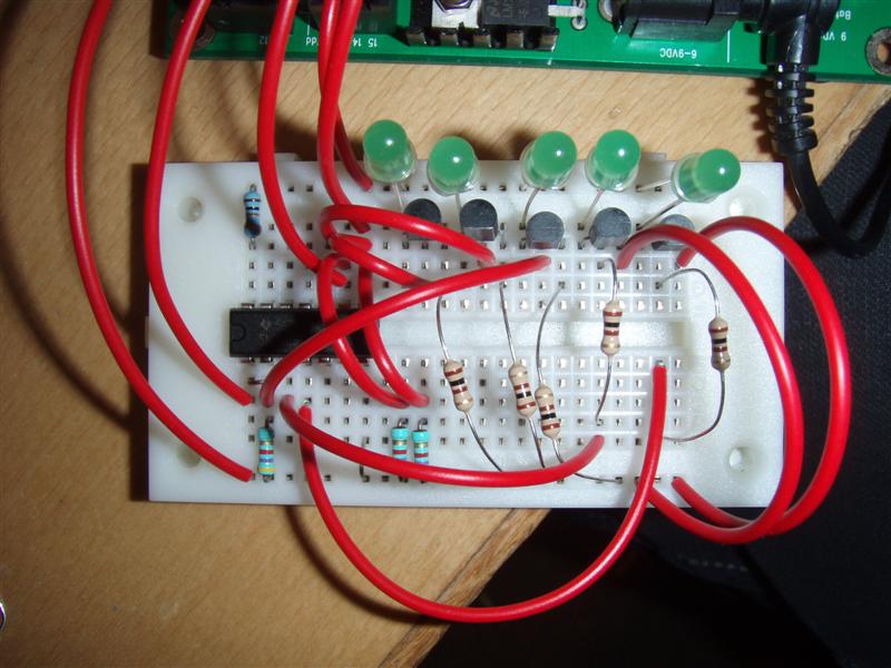
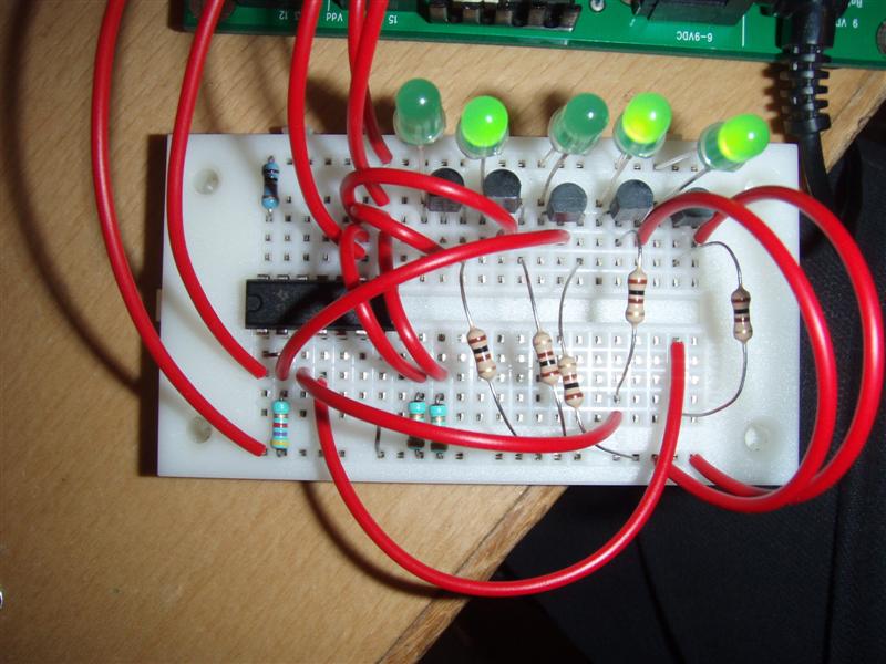
I hooked them up to a basic stamp with a breadboard as shown in the pictures with 4k7 pulldown resistors on the data, clock and reset lines and used transistors with leds to show the state of the data, clock, reset, Qa, and Qb flip flops.
heres the code i used:
' {$STAMP BS2}
LOW 13
PAUSE 1000
HIGH 13
PAUSE 1000
HIGH 15
PAUSE 1000
PULSOUT 14, 100
PAUSE 1000
LOW 15
PAUSE 1000
PULSOUT 14, 100
end
Ok so i was expecting Qa to be low (0) and Qb to be high (1) and i clocked two bits out of the basic stamp, 1, and 0.
all that happens is that i can see the data clocking because of the LEDs on the data lines and the pauses i included in the code but the LEDs on Qa and Qb remain the same.
i tried different transistor configurations and and different resistors on the transistors but nothing worked.
I dont know whether this is a hard ware issue such as voltage etc or a code issue.
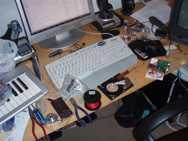
ive included photos of my circuit (and my *ULTRA* clean workspace) for reference
Please help me
Im not new to basic stamp and have been using a BS2 with the USB BOE for a while now (i was using picaxe before that).
anyway, i just ordered some 8 x 8 led matrices and was looking at ways to control them and decided to use a d flip flop ring counter to refresh the display and a serial in parallel out 8 bit shift register to sort of buffer the data that was going to be displayed on the next refresh of the matrix.
so i went to my local supplier and picked up four 74LS175 quad D flip flops for the counters and two 74LS164 8 bit shift registers, as well as 20 green LEDs and a multi pack of resistors for prototyping purposes.
i have never used shift registers before but i am familiar on how they work. eg i know how they shift data in on the clock pulse etc. . . i know the theory side of things.
I hooked them up to a basic stamp with a breadboard as shown in the pictures with 4k7 pulldown resistors on the data, clock and reset lines and used transistors with leds to show the state of the data, clock, reset, Qa, and Qb flip flops.
heres the code i used:
' {$STAMP BS2}
LOW 13
PAUSE 1000
HIGH 13
PAUSE 1000
HIGH 15
PAUSE 1000
PULSOUT 14, 100
PAUSE 1000
LOW 15
PAUSE 1000
PULSOUT 14, 100
end
Ok so i was expecting Qa to be low (0) and Qb to be high (1) and i clocked two bits out of the basic stamp, 1, and 0.
all that happens is that i can see the data clocking because of the LEDs on the data lines and the pauses i included in the code but the LEDs on Qa and Qb remain the same.
i tried different transistor configurations and and different resistors on the transistors but nothing worked.
I dont know whether this is a hard ware issue such as voltage etc or a code issue.
ive included photos of my circuit (and my *ULTRA* clean workspace) for reference
Please help me

800 x 600 - 96K
800 x 600 - 81K

800 x 600 - 97K
800 x 600 - 80K
800 x 600 - 85K
Comments
Take a look at the SHIFTIN and SHIFTOUT commands. They are used for accessing synchronous serial devices like shift registers. Two pins are used - one for the clock line, and one for the data line. If you understand how shift registers work, as you say, then the information in the PBASIC Help File or the PBASIC Refernce Manual should contain all the information you will need.
Regards,
Bruce Bates
▔▔▔▔▔▔▔▔▔▔▔▔▔▔▔▔▔▔▔▔▔▔▔▔
When all else fails, try inserting a new battery.
am i perhaps not connecting the LEDs the right way to the register?
does the shift register work with very small voltage differences or something?
Post Edit -- Zooming in on "117", there's some inconsistency in your placement of the 100Ω resistors vis-a-vis the transistors.· Again, the schematic would be helpful.
Post Edited (PJ Allen) : 9/26/2008 1:58:49 PM GMT
as i was drawing the schematic, i realized that i had a 10K resistor on the positive of the register and suddenly occurred to me that that was way too high a value for a 5v circuit so i reduced it to 1K and hey presto it works.
in the schematic ive left out the LEDs one the data lines but you can see those in the other pictures
Thanks
2) The 100 Ohm base resistors for the switching transistors are too low. You want a maximum base current of 20mA, probably more like 5mA. A resistor value of 1K Ohms is more appropriate.
3) For most conventional red LEDs, a 220 Ohm or 270 Ohm current limiting resistor is good. For other colors, you'll have to use Ohms Law to figure out the resistor based on the forward voltage of the LED and maybe 20-25mA of current or whatever the maximum current is.