

Thermal Imaging with Parallax's New Heat Sensor
 Phil Pilgrim (PhiPi)
Posts: 23,514
Phil Pilgrim (PhiPi)
Posts: 23,514
Parallax's new heat sensor, the MLX90614 Infrared Module is designed for non-contact measurement of temperature, averaged over a 90° field of view. Given, this wide field of view and a way to scan it, it occurred to me that it might be possible to construct a crude thermal imager.
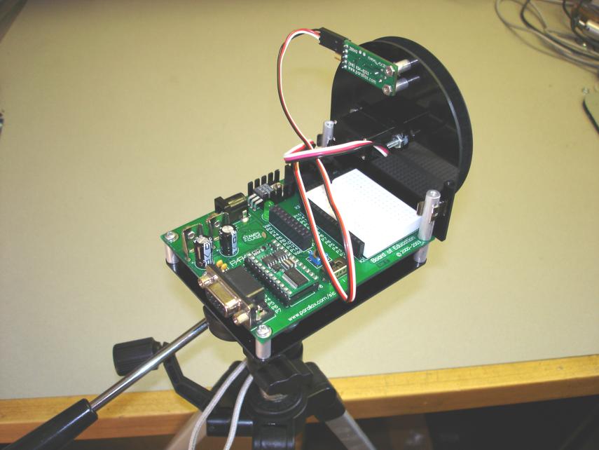
In the earliest days of experimental television, a rotating Nipkow Disk containing a spiraled set of holes, along with a single photodetector, was used to scan the televised subject, one "pixel" at a time. The same technique can be used for thermal scanning as well. I started by milling a disk out of a thin paper/phenolic laminate (i.e. machinable cardboard) that could be attached to a servo horn. In it, at 22° intervals, are eight small holes at a progression of radii from the center. As each hole passes the heat sensor, it scans one line of pixels. So with eight holes, I can get an eight-line scan. Here's a photo of the disk attached to the front of my "heat camera":

The disk is rotated with a miniature servo mounted to a piece of G10 fiberglass. The sensor module is mounted behind the G10 piece with a pair of spacers. In front of it, a small rectangular window has been cut into the G10 to restrict the field of view from the default circle to a square format. Here's a back view of the camera (a Board of Education with a BS2) mounted on a tripod:

Each of the eight scan lines consists of 25 pixels, so there are 200 pixels total. As the servo increments, each scanned pixel value is read from the MLX90614 module and saved in the BASIC Stamp's EEPROM as a full word. There is room in the BS2 for three "heat pictures" when saved this way. No attempt is made to relate the raw data from the sensor to actual temperatures. That would be futile, since the temperatures of the disk and of the fiberglass mount get averaged in. What I'm interested are just the temperature differences within the field of view. These are read into a PC program that scales them to cover the complete gamut from light to dark and assigns a false color value to each pixel (lighter = hotter). Following are some sample heat images, alongside photos of the same subjects in the visible spectrum.
First is a soldering iron clamped in a stand. At 500°F or so it provides a good contrast with the background:

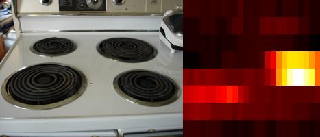
Next is a four-burner stove. One burner is set to medium; another, to warm. Can you tell which these are?

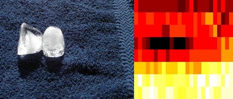
Last is a pair of ice cubes lying on a washcloth. Cold subjects are harder to image than warm ones. The reason is that the temperature difference with the background is smaller (32°F - 70°F for ice, versus 200°F - 70°F for a hot cup of coffee), so it's harder to get good contrast. A piece of dry ice would probably have made a much better picture.

The hardest part of this project (aside from designing the two mechanical parts) was determining the correct servo pulse width for the beginning of each line. This required a lot of trial and error to get right, and it still tends to drift a little. A solution would be a transmissive optical sensor scanning the unused half of the disk to detect another set of holes, which could be precisely positioned.
Does this imaging setup have any value other than as a novelty? Probably not — mainly because the resolution is so crude. Also, the signal-to-noise ratio is rather poor, since each hole in the disk is such a small fraction of the total field of view. Most of what the sensor sees at any point in the scan is the disk itself, whose temperature is unknown and can vary across its diameter. (An aluminum disk might be better, since any thermal gradients would equilibrate quickly.) Nonetheless, it was fun just seeing if it could be done.
Many thanks to Chuck Gracey (Ken and Chip's dad) for sending me the sensor module to try. Chuck wrote the code for it, by the way. It's an excellent product!
-Phil
Post Edited (Phil Pilgrim (PhiPi)) : 9/22/2008 1:00:35 AM GMT
In the earliest days of experimental television, a rotating Nipkow Disk containing a spiraled set of holes, along with a single photodetector, was used to scan the televised subject, one "pixel" at a time. The same technique can be used for thermal scanning as well. I started by milling a disk out of a thin paper/phenolic laminate (i.e. machinable cardboard) that could be attached to a servo horn. In it, at 22° intervals, are eight small holes at a progression of radii from the center. As each hole passes the heat sensor, it scans one line of pixels. So with eight holes, I can get an eight-line scan. Here's a photo of the disk attached to the front of my "heat camera":
The disk is rotated with a miniature servo mounted to a piece of G10 fiberglass. The sensor module is mounted behind the G10 piece with a pair of spacers. In front of it, a small rectangular window has been cut into the G10 to restrict the field of view from the default circle to a square format. Here's a back view of the camera (a Board of Education with a BS2) mounted on a tripod:
Each of the eight scan lines consists of 25 pixels, so there are 200 pixels total. As the servo increments, each scanned pixel value is read from the MLX90614 module and saved in the BASIC Stamp's EEPROM as a full word. There is room in the BS2 for three "heat pictures" when saved this way. No attempt is made to relate the raw data from the sensor to actual temperatures. That would be futile, since the temperatures of the disk and of the fiberglass mount get averaged in. What I'm interested are just the temperature differences within the field of view. These are read into a PC program that scales them to cover the complete gamut from light to dark and assigns a false color value to each pixel (lighter = hotter). Following are some sample heat images, alongside photos of the same subjects in the visible spectrum.
First is a soldering iron clamped in a stand. At 500°F or so it provides a good contrast with the background:
Next is a four-burner stove. One burner is set to medium; another, to warm. Can you tell which these are?
Last is a pair of ice cubes lying on a washcloth. Cold subjects are harder to image than warm ones. The reason is that the temperature difference with the background is smaller (32°F - 70°F for ice, versus 200°F - 70°F for a hot cup of coffee), so it's harder to get good contrast. A piece of dry ice would probably have made a much better picture.
The hardest part of this project (aside from designing the two mechanical parts) was determining the correct servo pulse width for the beginning of each line. This required a lot of trial and error to get right, and it still tends to drift a little. A solution would be a transmissive optical sensor scanning the unused half of the disk to detect another set of holes, which could be precisely positioned.
Does this imaging setup have any value other than as a novelty? Probably not — mainly because the resolution is so crude. Also, the signal-to-noise ratio is rather poor, since each hole in the disk is such a small fraction of the total field of view. Most of what the sensor sees at any point in the scan is the disk itself, whose temperature is unknown and can vary across its diameter. (An aluminum disk might be better, since any thermal gradients would equilibrate quickly.) Nonetheless, it was fun just seeing if it could be done.
Many thanks to Chuck Gracey (Ken and Chip's dad) for sending me the sensor module to try. Chuck wrote the code for it, by the way. It's an excellent product!
-Phil
Post Edited (Phil Pilgrim (PhiPi)) : 9/22/2008 1:00:35 AM GMT
855 x 642 - 65K

855 x 642 - 58K

442 x 200 - 17K
467 x 200 - 12K
471 x 200 - 22K
Comments
The heat sensor's also pretty good too. It looks like you've been reading too much Logie Baird.
▔▔▔▔▔▔▔▔▔▔▔▔▔▔▔▔▔▔▔▔▔▔▔▔
▔▔▔▔▔▔▔▔▔▔▔▔▔▔▔▔▔▔▔▔▔▔▔▔
Searider
reason so I was pleasantly surprised to see this.· Nice.
··················· Thank-you
Searider, the disk is moved incrementally. The MLX90614 sensor used in this module has a default settling time of 100ms, so a certain amount of "dwell" is required for each pixel. Also, in order to clear any influence from a prior line, the program sits for about a second at the beginning of each new line. Needless to say, a moving subject would be quite out of the question.
Subtracting a baseline reading for each line is an intriguing idea, if only to eliminate the effect of temperature gradients across the disk. You may have noticed that the first and third scans seem to get gradually warmer near the bottom, which may be due to such a gradient. An aluminum disk, as I suggested above, might render this step unnecessary, though.
-Phil
Post Edited (Phil Pilgrim (PhiPi)) : 9/23/2008 3:01:07 AM GMT
Chuck
-Phil
▔▔▔▔▔▔▔▔▔▔▔▔▔▔▔▔▔▔▔▔▔▔▔▔
'Still some PropSTICK Kit bare PCBs left!
-Phil
▔▔▔▔▔▔▔▔▔▔▔▔▔▔▔▔▔▔▔▔▔▔▔▔
'Still some PropSTICK Kit bare PCBs left!
▔▔▔▔▔▔▔▔▔▔▔▔▔▔▔▔▔▔▔▔▔▔▔▔
Chris Savage
Parallax Engineering
Typically one and a half to two feet. The stove picture may have been more like three. I haven't tried anything much further away yet. I was thinking that if I got my car warmed up, it might make a decent large subject — especially if I raise the hood.
I'm trying to figure out a way to get better vertical resolution without making the disk a lot larger. With a stepper, I could double it, since I could use both halves of the disk. But there are other possibilities using coded sequences of holes, rather than just a single hole at a time. These would involve some postprocessing, similar to that of a CT scan. They would also improve the s/n, since more of the subject would be visible at once.
-Phil
▔▔▔▔▔▔▔▔▔▔▔▔▔▔▔▔▔▔▔▔▔▔▔▔
'Still some PropSTICK Kit bare PCBs left!
Deno
A side note - I did not know that Chip and Ken's Dad was in the business too - Great to hear about Chuck!
▔▔▔▔▔▔▔▔▔▔▔▔▔▔▔▔▔▔▔▔▔▔▔▔
Whit+
"We keep moving forward, opening new doors, and doing new things, because we're curious and curiosity keeps leading us down new paths." - Walt Disney
What is the dwell time on each pixel? The MLX90614 data sheet shows a lot of options for programming its digital filters, and I'm curious if that is fixed at a particular setting in the Parallax module. The table on page 13 of the data sheet shows selections from 0.04 secondd to 4.5 seconds.
The graph on page 30 of the data sheet shows the response as a function of angle, and at 45 degrees it is down to about 25% of the value at 0 degrees. An IR lens in front of the sensor and motion of the lens or the whole assembly might produce a much stronger signal.
▔▔▔▔▔▔▔▔▔▔▔▔▔▔▔▔▔▔▔▔▔▔▔▔
Tracy Allen
www.emesystems.com
Or can drive the MLX90614 directly from a prop though its a pain, it has some max timings that must be obeyed and if you go wrong it goes silent. I ended up powering it from a prop pin so if it goes silent I can power it down and up again.
Chuck
Post Edited (CHIPKEN) : 9/30/2008 3:38:24 AM GMT
I just looked the parallax mlx90614 module says 20ms, as I said above I used the sensor directly and it only uses a few ma. I got the sensor a while ago and parallax shipping their module made me finally work out how to drive sensor.
Post Edited (Timmoore) : 9/29/2008 4:33:14 AM GMT
I'm using a 100ms dwell time between horizontal pixels, which I believe is the default time constant for the chip used in the module. I assume the internal filter is an IIR, so I allow an extra second at the beginning of each line for things to clear out. This may, of course, be overkill. I'm reluctant to reprogram the sensor for a faster filter, since my S/N is bad enough as it is from looking through that tiny hole.
I haven't investigated IR lenses yet. I'm guessing that, for these long wavelengths, they'd be very expensive. I need to see what Edmund Sci has got.
All,
Regarding Chuck's reminder to cut the power to write to ROM: Be sure to leave the power off for a ponderable length of time, too. I made the mistake, initially, of repowering too quickly and couldn't figure out why my settings weren't being saved.
-Phil
The kind of photography covered by the cited article involves near-infrared wavelengths (700 - 1000 nm). The Melexis heat sensor is sensitive to wavelengths between 5500 and 14000 nm, where ordinary glass and "clear" plastics are nearly opaque. Lenses for these wavelengths are made of specialized materials, such as this one, an unmounted plano convex IR lens selling for $142.
-Phil
Post Edited (Timmoore) : 9/29/2008 6:53:22 AM GMT
I was thinking comparatively, too, that a PIR sensor is more like an edge detector in that it responds to changes in temperature, whereas the Melexis sensor is a thermopile that has a response down to DC for measuring static temperature. The upper frequency limit on PIR is 1/10 or 1/20 second. I wonder about the Melexis. Below the IIR and FIR filters, however configured, there must also be some thermal mass of the thermopile and membrane.
Thanks for responding, Chuck. It is good to know that the parameter registers can be programmed. I was intrigued by the PWM output mode too. That can be turned into an analog output, right, for super simple measurement/control systems?
▔▔▔▔▔▔▔▔▔▔▔▔▔▔▔▔▔▔▔▔▔▔▔▔
Tracy Allen
www.emesystems.com
▔▔▔▔▔▔▔▔▔▔▔▔▔▔▔▔▔▔▔▔▔▔▔▔
Giggly Googley!
The one you've cited has a broader IR response (2 - 22 um vs. 5.5 - 14 um for the Parallax unit), which renders it more sensitive to near-IR interference from sunlight. However, it does include an eight-sensor array, instead of just one sensor, which may explain the high price.
-Phil
▔▔▔▔▔▔▔▔▔▔▔▔▔▔▔▔▔▔▔▔▔▔▔▔
Giggly Googley!
-Phil
▔▔▔▔▔▔▔▔▔▔▔▔▔▔▔▔▔▔▔▔▔▔▔▔
Giggly Googley!