

Problem with circuit, part failing
 metron9
Posts: 1,100
metron9
Posts: 1,100
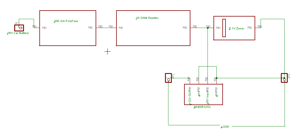
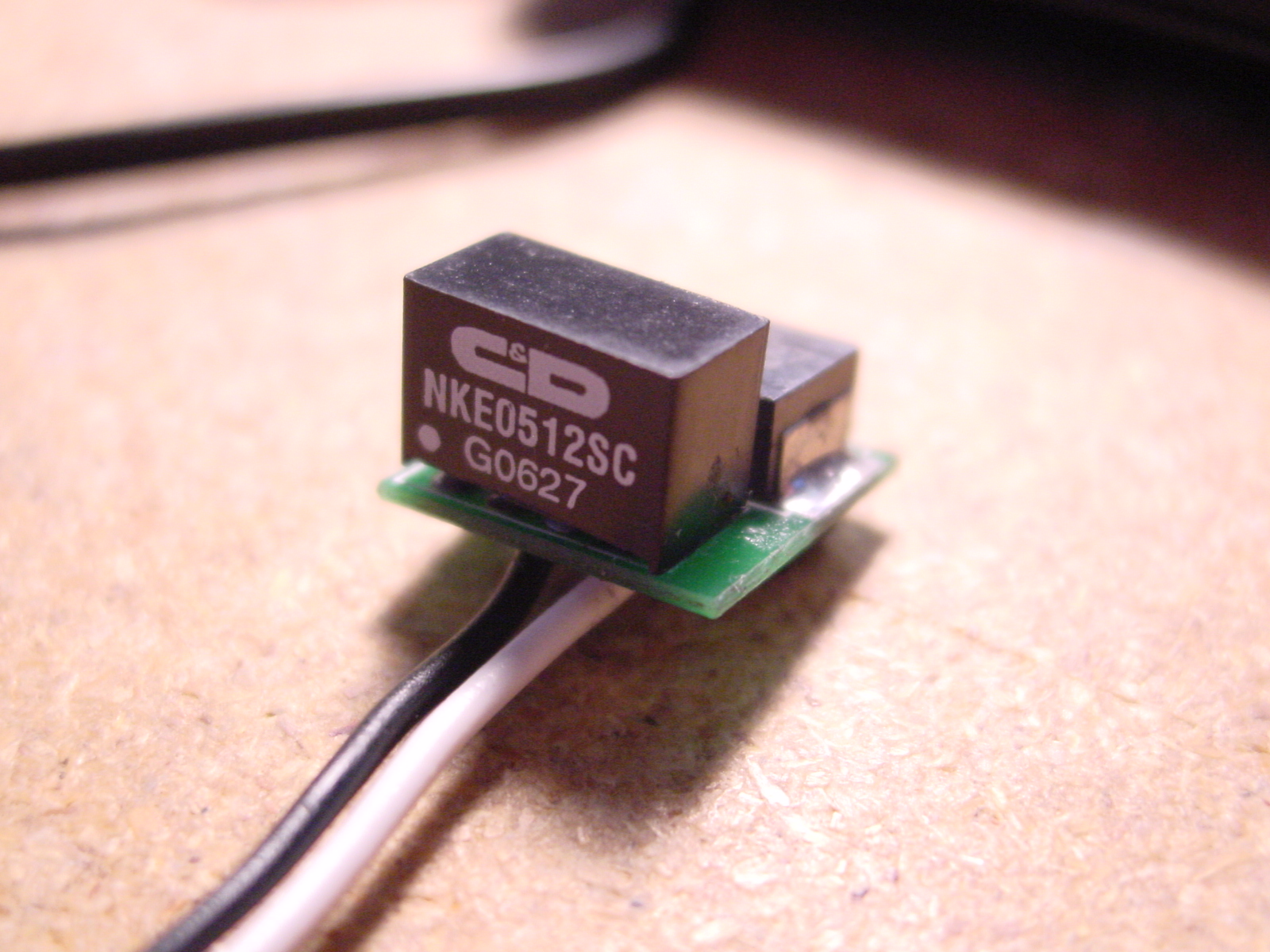
I have a circuit that is used for 6V cars that powers a 12V Tach. The Dc-dc converter is failing and i don't know why. Perhaps the grounds tied together? I did just realize the dc-dc part uses a isolated tiny transformer.
Does anyone see a problem with the circuit? I have bench tested it at up to 12V and the polyfuse does its job shutting it down before it can overheat.
http://www.cd4power.com/data/power/ncl/kdc_nke.pdf
▔▔▔▔▔▔▔▔▔▔▔▔▔▔▔▔▔▔▔▔▔▔▔▔
Think Inside the box first and if that doesn't work..
Re-arrange what's inside the box then...
Think outside the BOX!
Post Edited (metron9) : 9/17/2008 11:59:49 PM GMT
Comments
Rated output current 83mA.
Does it "fail" with a load other than this tachometer?
A much better choice would be to use an LM2940-5.0 regulator ahead of the DC-DC converter. They have a low dropout voltage and were designed for automotive use.
-Phil
▔▔▔▔▔▔▔▔▔▔▔▔▔▔▔▔▔▔▔▔▔▔▔▔
'Still some PropSTICK Kit bare PCBs left!
When I short the output through a 100ohm resistor it only shows 80mA through the resistor and drops to around 40 as the polyfuse heats up
Shorting the output fully initially draws 250mA from a 7V supply and drops as expected as the poly fuse heats up
Still works fine after shorting as a matter of fact the one he gave me he said did not work and it works just fine.
I think I will take all the parts he has that he got back and test them, perhaps it is operator error.
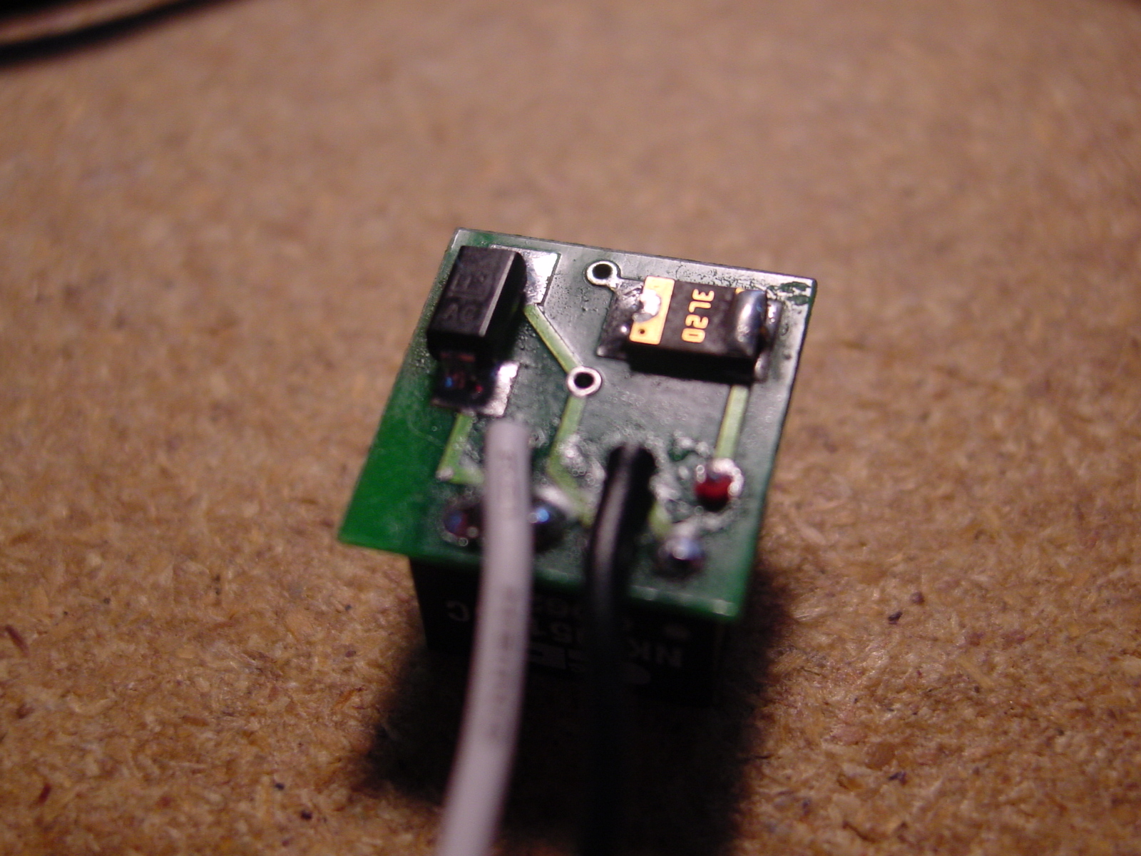
By the wau the RED input wire is not pn the picture above. The white wire is the 12V output.
I am making some assumptions that the car voltage is at least 7V while running due to the alternator, the part runs stable from 7V up to almost 11 volts, past 11 volts the 200 ohm poly fuse starts to heat up and lowers the voltage.
▔▔▔▔▔▔▔▔▔▔▔▔▔▔▔▔▔▔▔▔▔▔▔▔
Think Inside the box first and if that doesn't work..
Re-arrange what's inside the box then...
Think outside the BOX!
http://parts.digikey.com/1/parts/421798-diode-zener-3w-5-1v-smb-1smb5918bt3g.html
However the part on the board says AG on it and is not the same part, it is a ltiile narrower than the above part so I will have to find out what he bought for parts.
The maximum though should be only 200mA and at 10.5V it is running at 100mA
I am running it now and it is about 125 F while the polyfuse is at 93F thats at 10.5V and I hope a 6V alternator connected to a battery is below that.
▔▔▔▔▔▔▔▔▔▔▔▔▔▔▔▔▔▔▔▔▔▔▔▔
Think Inside the box first and if that doesn't work..
Re-arrange what's inside the box then...
Think outside the BOX!
Pin left to right is -in +in -out +out· and indeed the grounds are not tied together so I think that may have something to do with not working parts at some point but it seems to function fine with the grounds together. I will try and see if there is any difference using just one of regulators and then with and without the grounds tied together.
Could the oscillation be from the current through the toroidal inductor so it generates its own pulse like the jewel thief circuit?
·
I removed the inductor so I could see what was under it.
▔▔▔▔▔▔▔▔▔▔▔▔▔▔▔▔▔▔▔▔▔▔▔▔
Think Inside the box first and if that doesn't work..
Re-arrange what's inside the box then...
Think outside the BOX!
Post Edited (metron9) : 9/18/2008 7:45:38 AM GMT
-Phil
▔▔▔▔▔▔▔▔▔▔▔▔▔▔▔▔▔▔▔▔▔▔▔▔
'Still some PropSTICK Kit bare PCBs left!
▔▔▔▔▔▔▔▔▔▔▔▔▔▔▔▔▔▔▔▔▔▔▔▔
Think Inside the box first and if that doesn't work..
Re-arrange what's inside the box then...
Think outside the BOX!
I disagree with the zener diode "regulator" thing you're doing.· You have a 10Ω resistor in series with your load.· With 80mA out, your boost module is taking nearly 250mA in; no achievement in efficieny there.· Brash assumption, 40mA out means 125mA in; 125mA x 10Ω = 1.25V, 6V - 1.25V = 4.75V, getting marginal.· The range is 4.5 - 5.5V.· When it is further subjected to environemntal heat then that takes us further into Derating Land.
Since I don't have an education in electronics, it just seemed to me that dropping a couple of volts using a zener for a circuit that only takes 40mA would be what a zener is designed for, but obviously not. What is the overall easy to understand reason the zener voltage regulator is a bad idea in this circuit, because of the boost module? If for example you had a circuit with one 40 mA LED a resistor and a zener to regulate voltage, how is that different with reguard to the dc-dc boost? Assuming a zener voltage clamp would be a good circuit for varying voltage input to drive a 40ma LED.
▔▔▔▔▔▔▔▔▔▔▔▔▔▔▔▔▔▔▔▔▔▔▔▔
Think Inside the box first and if that doesn't work..
Re-arrange what's inside the box then...
Think outside the BOX!
·