

again trying to find some sort of documentation. Have you seen this board
 Badger
Posts: 184
Badger
Posts: 184
Hello
i have emails to the place i bought this from to give me more documentation but i have yet to here from them. if anyone has seen or used this board could you point me in the direction of information.. I bought if from micro4you.com
i have emails to the place i bought this from to give me more documentation but i have yet to here from them. if anyone has seen or used this board could you point me in the direction of information.. I bought if from micro4you.com
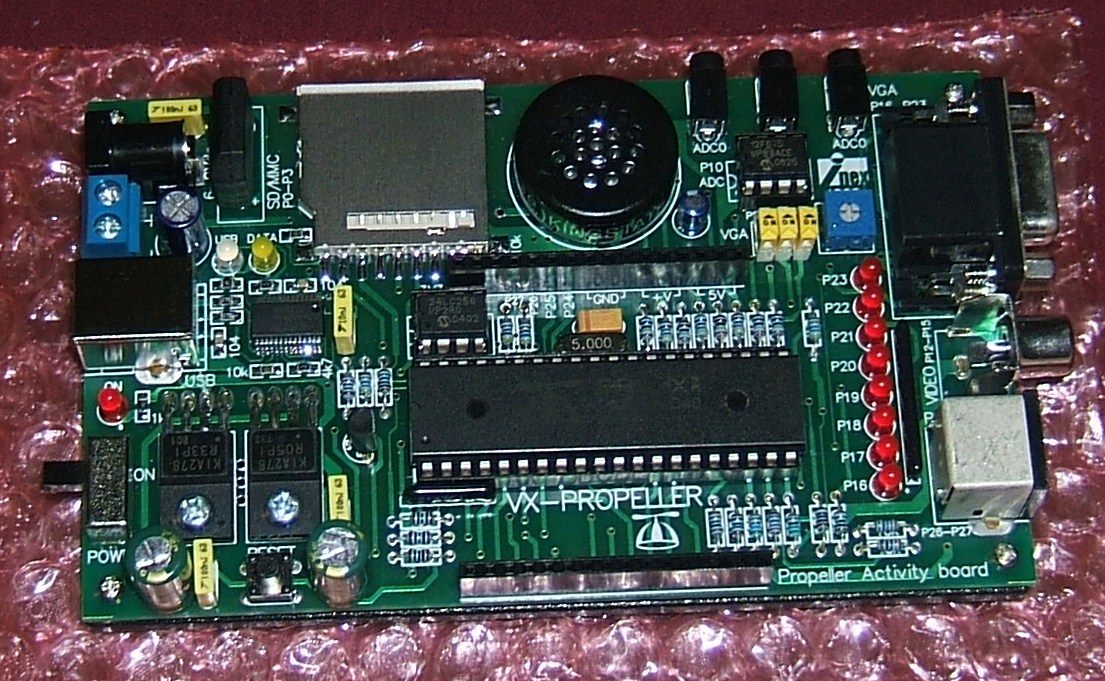
1105 x 681 - 278K
Comments
Found the attached files via e-bay in France!!
That seller supplied sample source code. At least with the schematic and component names you should be able to get up and going with the standard docs and code found here. Good luck.
▔▔▔▔▔▔▔▔▔▔▔▔▔▔▔▔▔▔▔▔▔▔▔▔
Propeller Wiki: Share the coolness!
Chat in real time with other Propellerheads on IRC #propeller @ freenode.net
It's not quite the same board. Sorry!!
▔▔▔▔▔▔▔▔▔▔▔▔▔▔▔▔▔▔▔▔▔▔▔▔
Propeller Wiki: Share the coolness!
Chat in real time with other Propellerheads on IRC #propeller @ freenode.net
thanks for looking i got in touch with micro4you through there almost non used forums. he is trying to write a test manual for it. all the docs that come with it are fro the proto board and a couple of others boards from parallax. this is a nice board for 80 dollars but gee i dont know much about this kind of stuff and i am going crazy .. I will look at these anyway may give me an idea. the schematic he gave me shows 14 pin headers the card has 16 pin headers so i dont know are all the pins are and the grounds and such. due to some of them being in the middle of the header. so i dont want to blow up my censors cant afford to replace them ..
badger
-Phil
▔▔▔▔▔▔▔▔▔▔▔▔▔▔▔▔▔▔▔▔▔▔▔▔
'Still some PropSTICK Kit bare PCBs left!
Perhaps they can just give you a schematic?
Might be worth a quick e-mail.
▔▔▔▔▔▔▔▔▔▔▔▔▔▔▔▔▔▔▔▔▔▔▔▔
Propeller Wiki: Share the coolness!
Chat in real time with other Propellerheads on IRC #propeller @ freenode.net
thanks for the manufacture name been looking for that. i am working with micro4you the seller i bought it from a man by the name of Soboom Sbon says he is writing a test manual for this board .. when it is done ???? but that is all i know. he is doing this through www.friendlyarm.com i hope i can post these websites and not be against the rules i am just letting all of those who wish to help know ware i have been.
Badger
they gave me a schematic but it dont seem to match it shows 14 pin headers and the board has 16 pin headers i will post the schematic they gave me and you look at it and tell me if i am off my rocker ok .. as i said i dont know very much about this stuff yet but i am pushing my self to learn.
Badger
I haven't studied it all, but this looks like a pretty good schematic to me. As far as the headers, if you look on the board itself, it looks like the duplicated the connections indicated on the schematic to a couple of pins (for example 3 - 5 volt pins instead of 2 on header marked port 2 and the same is true of +V on the same header and this would account for the two extra header pins·- I could not see the connection on the Port 1 header on the actual board). But otherwise, I found the schematic pretty accurate based on the time I looked. Maybe someone more experienced will see something else, but I think you basically have it now.
▔▔▔▔▔▔▔▔▔▔▔▔▔▔▔▔▔▔▔▔▔▔▔▔
Whit+
"We keep moving forward, opening new doors, and doing new things, because we're curious and curiosity keeps leading us down new paths." - Walt Disney
Post Edited (Whit) : 9/16/2008 6:58:25 PM GMT
Unless the headers are clearly marked you probably want to do that anyway and I'd do it as a precaution anyway in case the documentation / schematic doesn't match what the board actually is.
You can remove the Propeller Chip if you're worried about damaging it during such testing.
never thought of that one .. i have studied the traces with a magnifiing glass. I am not really all that good with a multimeter but i do know how to do continuity. My digital is a little strange but i do have an analog meeter that works well for this task. . Will or can doing this damage the propeller chip in anyway. i know they are not all that expensive but then again. paying attention this time of month with school starting is penny pinching and as hard as we pinch you can here the penny protest. LOLOL.. but anyway all joking put aside. can it damage it if i touch something shorted if the power is off. or not hooked to the board.
Badger.
and thanks again for posting i thought this thread was dead.
been thinking .. ouch. what you mean is to check the pin on the header to what pin matches on the cpu correct.
and then what pins are gound. is the 3.3 and 5v connected to the cpu as well and if i may ask it has pins labeled v+ what is this and what is the voltage for theses pins. its power chips has 4 pins the others have 3 just for information.
badger
hope you can understand what i am trying to say sometimes i dont explain things very well