

Reflective surface dector circuit
 Kye
Posts: 2,200
Kye
Posts: 2,200
Hello,
I'm trying to build a reflective object sensor to be used in an array to make a line following robot.
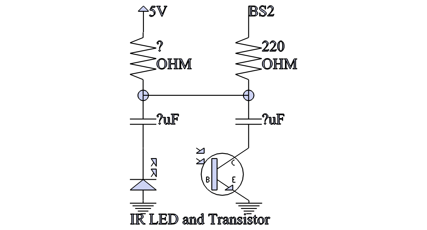
I plan to use this circuit attached.
1.·Its operation works by pulling the BASIC stamp pin to low.
2. Then waiting for the capacitors to discharge.
(When the capacitors are charging the LED will blink once quickly and cause the transistor to ground the other capacitor, the idea is that a reflective object will reflect the light from the LED back to the transistor. The RC time command is there to measure the change is time created by the transistor controlled capacitor and not the LED one.)
3. Afterward executing the RC time command and waiting for the voltage on the capacitors to rise from 0v to 1.4v.
I'm not interested particularly in other ways to make a line following robot -· I already know them, if you have any suggestions to make this circuit better or what values I should use please give feedback. Thank you.
OH! I built this circuit using reference ideas from the parallax qti sensor and from the reference material on the rc time command. I would actually prefer to reverse logic operation and ground and power nodes on the circuit so I could watch the capacitor discharge from 5v to 1.4 but·I only have npn photo transistors so I can't reverse the circuit.
▔▔▔▔▔▔▔▔▔▔▔▔▔▔▔▔▔▔▔▔▔▔▔▔
Nyamekye
I'm trying to build a reflective object sensor to be used in an array to make a line following robot.
I plan to use this circuit attached.
1.·Its operation works by pulling the BASIC stamp pin to low.
2. Then waiting for the capacitors to discharge.
(When the capacitors are charging the LED will blink once quickly and cause the transistor to ground the other capacitor, the idea is that a reflective object will reflect the light from the LED back to the transistor. The RC time command is there to measure the change is time created by the transistor controlled capacitor and not the LED one.)
3. Afterward executing the RC time command and waiting for the voltage on the capacitors to rise from 0v to 1.4v.
I'm not interested particularly in other ways to make a line following robot -· I already know them, if you have any suggestions to make this circuit better or what values I should use please give feedback. Thank you.
OH! I built this circuit using reference ideas from the parallax qti sensor and from the reference material on the rc time command. I would actually prefer to reverse logic operation and ground and power nodes on the circuit so I could watch the capacitor discharge from 5v to 1.4 but·I only have npn photo transistors so I can't reverse the circuit.
▔▔▔▔▔▔▔▔▔▔▔▔▔▔▔▔▔▔▔▔▔▔▔▔
Nyamekye
1374 x 742 - 29K
Comments
▔▔▔▔▔▔▔▔▔▔▔▔▔▔▔▔▔▔▔▔▔▔▔▔
Nyamekye
▔▔▔▔▔▔▔▔▔▔▔▔▔▔▔▔▔▔▔▔▔▔▔▔
·"If you build it, they will come."
-Phil
▔▔▔▔▔▔▔▔▔▔▔▔▔▔▔▔▔▔▔▔▔▔▔▔
'Still some PropSTICK Kit bare PCBs left!
▔▔▔▔▔▔▔▔▔▔▔▔▔▔▔▔▔▔▔▔▔▔▔▔
Nyamekye
Note that all this applies to homegrown sensors where you·"roll your own" from·discrete LEDs & PTXs.·One excellent integrated sensor·is the Hamamatsu P5587, a bargain at $2.25·from http://www.junun.org/MarkIII/Store.jsp. It is·well-thought out and·the LED & PTX are optically isolated from each other already.·It also contains·internal signal conditioning circuitry. This·sensor is quite useful both for line-following and reading optical encoders.
Have a look at the new Pololo 3pi robot and its line-following sensors. It has amazing speed and accuracy, yet its sensors are·tiny, relatively high (~1/2 inch) above the floor and have no external optical shutters. It's a very nice piece of engineering.
http://www.pololu.com/catalog/product/975·Watch all the videos. Slow to load, but fascinating to see.
▔▔▔▔▔▔▔▔▔▔▔▔▔▔▔▔▔▔▔▔▔▔▔▔
·"If you build it, they will come."
Post Edited (erco) : 9/13/2008 3:04:02 AM GMT
Yeah my circuit will never work since I can't discharge the capacitors. I forgot that the diode won't conduct unless it has some voltage across it and that the transistor won't conduct either without some light. (I'm an amateur)
Stupid... Thanks for the help Erco, I can use your circuit.
▔▔▔▔▔▔▔▔▔▔▔▔▔▔▔▔▔▔▔▔▔▔▔▔
Nyamekye