

the right transistor to drive a motor
 agfa
Posts: 295
agfa
Posts: 295
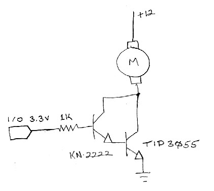
i want to drive a motor /variable speed /one direction /using PWM.· motor supply is 14v but will be 12v. stall current is 8 A.
using the components i have on hand i tested the circuit attached but used 5v (continuous)·as a test i/o. seems to work ok, but i have·a few questions that i couldn't find answers to.
*i question whether or not i am getting saturation.· i measure approx. .9 v at collector, and transistor (tip3055)·runs very hot.
*will the transistor operate cooler at full saturation?· I will be using a heatsink.
*will the darlington arrangement i have be able to handle PWM ok?· i seem to remember posts saying there could be an issue with some PWM freqs.
*how can switching speed be determined with a darlington?· tip3055=2MHz (min) & kn2222=250MHz.
*how can total gain be determined with hFE specs, tip3055@ IC-1A= 55 to 150 & kn2222 IC-150mA 100 to 300? seems like·a broad range.
421 x 376 - 59K
Comments
Things that contribute to heat dissipation: saturation voltage, load current, base current. The base voltage is fixed by the physics.
PWM ... the issue is that Darlingtons aren't as fast as single transistors. You determine the switching speed from the datasheet or from experimentation.
hFE is the gain. It's normally given as a broad range because that's what it really is. If you see a narrower gain range, the devices are probably tested and selected and the cost reflects that. The gain also varies somewhat with the current.
Post Edited (agfa) : 9/10/2008 10:55:39 PM GMT
www.st.com/stonline/products/literature/ds/12350.pdf
hey if you go out to i think the spelling is pololu.com you will have to check on that . you can google the following micro dual motor controller and find it.
it is .9 x .45 in size will handle 2 motor with 127 speed settings forward and reverse. Will connect to an external power sourse and only use to pin on the pic board. it has built in brown out circuits and such and a few more things i can remember. the partial assembled kit delivered to my address here in mid ohio is 22.90 it is a good buy for the price.. oh by the way if you wish to have more than on. i think you can daisy chain several together and control them from the pic board .. it is the best choice all around to building and designing your own... if you wish to build your own they offer all the indivigual parts for this as well.
badger
Another reason not to use a Darlington for high current demands is that between the C-E (Collector-Emitter) junction, you have a 1.2V drop where as with a standard bi-polar transistor the voltage drop is only 0.6V. In either case however with an 8 Amp load, I would consider using a MOSFET with a low Rds value.
Here is an Example with a 12V supply under an 8 Amp load....
With a Darlington, since it will automatically drop 1.2V, it will need to dissipate 9.6 Watts of wasted heat (P = I*V = 8A * 1.2V = 9.6 Watts)
With a bi-polar, since it will automatically drop 0.6V, it will need to dissipate 4.8 Watts of wasted heat (P = I*V = 8A * 0.6V =·4.8 Watts)
If a MOSFET (IRLZ44Z as an example) with an Rds of 0.0135 Ohms is used, you have a voltage drop of about 0.108V (V = I*R = 8A * 0.0135 Ohms = 0.108V)
With a 0.108V drop across the MOSFET, it will need to dissipate only 0.864 Watts of wasted heat. (P = I*V = 8A * 0.108V =·0.864 Watts)
http://www.irf.com/product-info/datasheets/data/irlz44z.pdf
▔▔▔▔▔▔▔▔▔▔▔▔▔▔▔▔▔▔▔▔▔▔▔▔
Beau Schwabe
IC Layout Engineer
Parallax, Inc.
Beau, thanks for the explaination.· i have a better understanding now.
btw, i did try it with an actual 5v pwm.··to big of a hurry to·use a heatsink or a protection diode.· it worked great for about 30·seconds.
thanks again guys.
agfa
thanks
Alex
For some reason your turtle avatar requires QuickTime on my computer and doesn't show up unless I load it into a separate page. Can you change it to a JPEG or GIF?
-Phil
▔▔▔▔▔▔▔▔▔▔▔▔▔▔▔▔▔▔▔▔▔▔▔▔
'Still some PropSTICK Kit bare PCBs left!
-Alex
"Can the gate be driven directly from a propeller output pin?" ... Not a good idea. Transistors are current devices, the B-E junction of a transistor likes to stay around the band-gap voltage to operate. For a bi-polar transistor this band-gap voltage is typically 0.6V. For a Darlington this band-gap voltage is typically 1.2V or two band-gap voltages. A resistor is used to adjust the current applied to the transistor at the B-E junction. The voltage near the B-E junction will generally stay near the band-gap voltage or near two band-gap voltages for Darlington transistors. If you exceed the band-gap (or two) voltages, then you can "burn-out" your transistor.
http://forums.parallax.com/attachment.php?attachmentid=37701
▔▔▔▔▔▔▔▔▔▔▔▔▔▔▔▔▔▔▔▔▔▔▔▔
Beau Schwabe
IC Layout Engineer
Parallax, Inc.
Also of concern is the Propeller's 3.3V "high" output. Many MOSFETs, including some "logic" MOSFETs won't turn completely on with such a low gate voltage. Be sure to check the RDS vs. VGS graphs in the datasheet. The gate threshold, by itself, is not a reliable indicator of the gate voltage required to drive a load.
-Phil
▔▔▔▔▔▔▔▔▔▔▔▔▔▔▔▔▔▔▔▔▔▔▔▔
'Still some PropSTICK Kit bare PCBs left!
Post Edited (Phil Pilgrim (PhiPi)) : 9/13/2008 7:21:36 PM GMT
Sorry I misread the post, Phil is right. The 'gate' of a MOSFET is capacitive and can be directly connected, but you need to observe the in-rush current effects mentioned in the previous posts or you can destroy the capacitor. With a bi-polar transistor however (including a Darlington) you must have a resistor on the 'base' to limit the current.
▔▔▔▔▔▔▔▔▔▔▔▔▔▔▔▔▔▔▔▔▔▔▔▔
Beau Schwabe
IC Layout Engineer
Parallax, Inc.