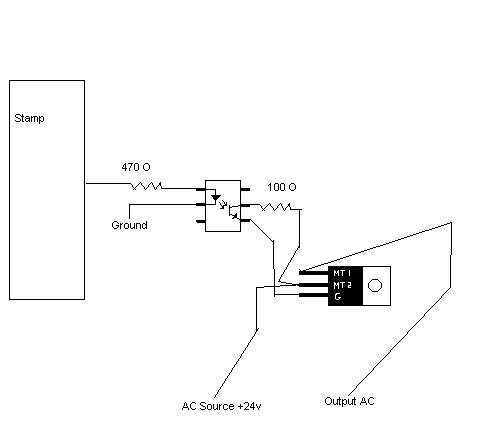
Triac - am I doing this right.
I need to switch 24V AC (furnace control)
I have a opto coupler - 4N35 -·(AKA-SPX7005) http://docs.bgmicro.com/pdf/ics4N35.pdf
I have a Triac - Q6008RH4 -(AKA-Q1257) http://www.teccor.com/data/en/Data_Sheets/E4AlternistorTriac.pdf
Ive looked over the datasheets, checked some examples, but I wanted one last check before I sent 24VAC coursing through my stamp or something.
So please let me know if you see any problems. This will be very slow switching, and on for a long time, if that matters.
Here is my proposed schematic for one circuit


Comments
http://www.epanorama.net/circuits/semiconductor_relays.html#triacuse
These are actually called alteristors. I dont know, they were 33 cents each, I grabed them to learn with.
Some optocouplers and phototransistors are two wires on the output side and others are three output. The third lead is to allow a negative bias. In that way, the extra lead allows you to fine tune the levels of on and off.
If the triac is not connected to the optocoupler and still leaks, that would be the source of your problem.
▔▔▔▔▔▔▔▔▔▔▔▔▔▔▔▔▔▔▔▔▔▔▔▔
It's sunny and warm here. It is always sunny and warm here.... (unless a typhoon blows through).
Tropically, G. Herzog [noparse][[/noparse] 黃鶴 ] in Taiwan
Post Edited (Kramer) : 9/11/2008 3:43:38 PM GMT
2) A triac has two states: conducting and not conducting.· When conducting --·it's a low resistance.· When not conducting --·it's a high resistance, but it's not an open circuit.
Skylight, what do you mean put enough load, like a big motor? See I'm basically logic switching here, the 24VAC signal just tells the furnace to turn on the fan\cool\heat. So will a triac not work in this case? Should I put a pulldown resistor of some sort on the fan\cool\heat signal lines?
I guess I could just go with relays, I only got the Triacs because they were cheap and I wanted to learn how to use them for the future.
▔▔▔▔▔▔▔▔▔▔▔▔▔▔▔▔▔▔▔▔▔▔▔▔
It's sunny and warm here. It is always sunny and warm here.... (unless a typhoon blows through).
Tropically, G. Herzog [noparse][[/noparse] 黃鶴 ] in Taiwan
Id still like to know what is wrong with the circuit.
Ive got some realys I guess I could just use them.
You have a phototransistor on the triac gate.· You are not triggering both alternations ("half-cycles.").
·
If not, the best choice might be a low voltage relay without any leakage. If the relay requires less than 20ma, if may be driven by the BasicStamp directly. Otherwise, you need to insert a 2n2222 to drive the relay and it may require 6 volts to actually supply 5 volts to the relay.
Apparently Triacs prefer a heavy load to better perform. Since this is not a heavy load or a high voltage, a relay should last a long time. Relay contacts actually last longer with AC than DC.
▔▔▔▔▔▔▔▔▔▔▔▔▔▔▔▔▔▔▔▔▔▔▔▔
It's sunny and warm here. It is always sunny and warm here.... (unless a typhoon blows through).
Tropically, G. Herzog [noparse][[/noparse] 黃鶴 ] in Taiwan