

DS1307 RTC via I2C to the Propeller, dealing with a 5 volt signal
 ElectricAye
Posts: 4,561
ElectricAye
Posts: 4,561
Hi all,
I'm planning on using a DS1307 real time clock with my Propeller and I have pored over the following thread:
http://forums.parallax.com/forums/default.aspx?f=25&p=1&m=124837
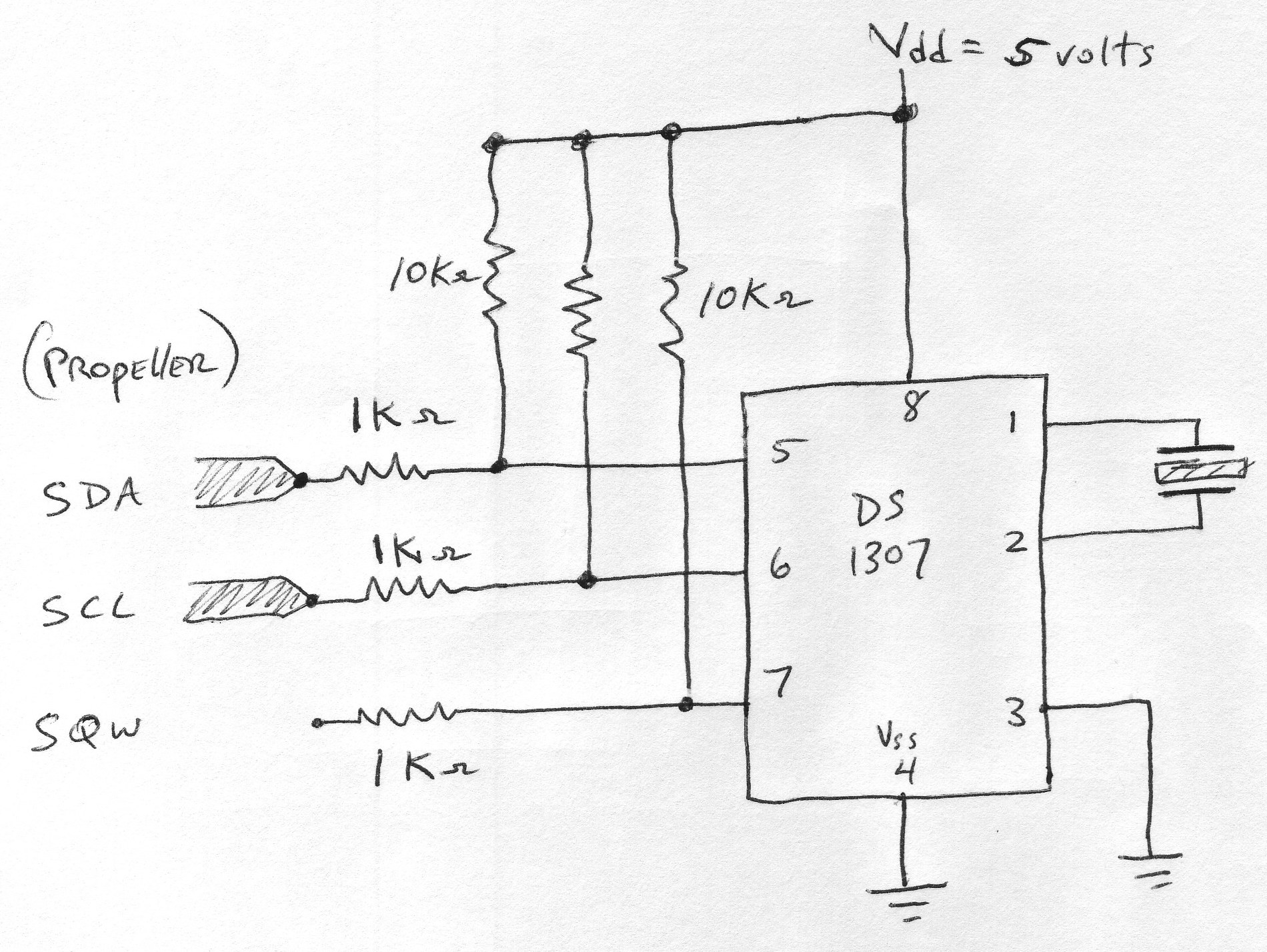
Contained within that thread are the thoughts and feelings and sentiments and guesses of many people concerning interfacing 5 volts to the Propeller. The conclusion I've come to is that I should be able to use 10K resistors for pullups and 1K resistors in series to cut down on too much current. Submitted for your approval: one schematic. In lieu of approval, I'd appreciate comments, suggestions, even outright ridicule if it will prevent me from smoking my chips. Will this work?
many thanks,
Mark
I'm planning on using a DS1307 real time clock with my Propeller and I have pored over the following thread:
http://forums.parallax.com/forums/default.aspx?f=25&p=1&m=124837
Contained within that thread are the thoughts and feelings and sentiments and guesses of many people concerning interfacing 5 volts to the Propeller. The conclusion I've come to is that I should be able to use 10K resistors for pullups and 1K resistors in series to cut down on too much current. Submitted for your approval: one schematic. In lieu of approval, I'd appreciate comments, suggestions, even outright ridicule if it will prevent me from smoking my chips. Will this work?
many thanks,
Mark
1900 x 1428 - 591K
Comments
I don’t have any advice on your connection…at least nothing that hasn’t already been covered in the linked thread. I do have a question though. Why not just use the DS1302? It is in the same class as the DS1307, has similar features and runs from 3.3V.
▔▔▔▔▔▔▔▔▔▔▔▔▔▔▔▔▔▔▔▔▔▔▔▔
Chris Savage
Parallax Engineering
My preference would be to have the 10K resistors only on lines which are open-collector or tri-state ouputs (from the DS1307). The series resistors are only required when a 5v device is driving the Prop; then you want to limit the current into the Prop if it is pulled above the 3.3v level.
The two resistors, the way you show them, provides a voltage divider of 1/11th for the Prop driving a device. This will reduce the signal to the device; in some cases may pose a problem. Just something to keep in mind.
▔▔▔▔▔▔▔▔▔▔▔▔▔▔▔▔▔▔▔▔▔▔▔▔
Harley Shanko
I guess I picked the DS1307 instead of the DS1302 because I'm clueless.· I saw the object for the DS1307 on the Obex and just blindly assumed there would be no hair-pulling issues.· It wasn't until today, just as I was wiring up the DS1307,·that I noticed the need for 5 volts and saw the potential for problems.· Only then did I freak.·
I think you're correct: I was worried about running out of pins so I wanted to use the DS1307 because it can be called by an address on a single I2C set of lines.
Mark
Post Edited (ElectricAye) : 9/4/2008 1:30:45 AM GMT
http://www.rayslogic.com/propeller/ProtoSched.gif
▔▔▔▔▔▔▔▔▔▔▔▔▔▔▔▔▔▔▔▔▔▔▔▔
Chris Savage
Parallax Engineering
I need to look into this 3.3volt I2C more closely.· I bet they only come in SOICs or something.· In the meantime I'll see how - or if - I can get my present DS1307 to work without fireworks.
wish me luck,
Mark
I had never thought of that.· Thanks for the idea!
Mark
yes, I recall this now.· I meant to ask you where you got a breakout board for this chip.· I guess I'll have to invest in a real soldering iron and hang up my Walmart special.
There are others around but they are either more expensive or take ~4 weeks to arrive. e.g. http://www.futurlec.com/SMD_Adapters.shtml
http://forums.parallax.com/showthread.php?p=604475
in the accompanying circuit diagram, Beau suggests supplying 3.3V to a DS1307 ?
The Datasheet specifically states a minimum supply voltage of 4.5V, will it work at 3.3V? probably, but your mileage may vary.
I've used a similar circuit to your drawing in the first post in this thread. I used the same i2c lines as the boot EEPROM, which are pulled to 3.3V with 4.7K resistors already (SpinStudio mainboard) I then used 1K resistors between the i2c bus and the DS1307. I connected the DS1307 supply to 5 Volts on my RTC ProtoCard.
▔▔▔▔▔▔▔▔▔▔▔▔▔▔▔▔▔▔▔▔▔▔▔▔
Brian
uController.com - home of SpinStudio - the modular Development system for the Propeller
PropNIC - Add ethernet ability to your Propeller! PropJoy - Plug in a joystick and play some games!
SD card Adapter - mass storage for the masses Audio/Video adapter add composite video and sound to your Proto Board
the idea of running the DS1307 on 3.3 volts is tempting, since I have only a couple chips to play with right now and I'm trying to create a strategy of testing configurations that will "fail safe" and work my way from there. Also, I'm grateful you posted an example that worked for you, and your set-up sounds the most promising so far.
a thousand thanks,
Mark
The i2c pins only sink, they don't source.· So, it can't harm the Prop. ·Adding resistors (beyond the existing pullups) may actually limit performance.
The nice thing about the DS1307 in particular, is that it recognizes 3.3V as logic high, even when powered by 5V...
Post Edited (Rayman) : 9/4/2008 10:17:48 AM GMT
not only is that excellent news but it helps me understand how these chips talk to each other. The pins merely drop a voltage that is already supplied on the line (thanks to the pull up resistors) and do not "inject" a voltage of their own. Awesome.
you made my day,
thanks,
Mark