

Why my 5Mhz crystal is slightly faster than 5Mhz?
 william chan
Posts: 1,326
william chan
Posts: 1,326
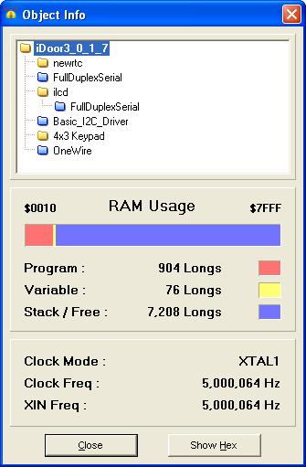
I saw in the Info Dialog (see attached) that my frequency is 5,000,064 Hz.
Did the Propeller sample this frequency and relay this info to the IDE?
▔▔▔▔▔▔▔▔▔▔▔▔▔▔▔▔▔▔▔▔▔▔▔▔
www.fd.com.my
www.mercedes.com.my
Did the Propeller sample this frequency and relay this info to the IDE?
▔▔▔▔▔▔▔▔▔▔▔▔▔▔▔▔▔▔▔▔▔▔▔▔
www.fd.com.my
www.mercedes.com.my
335 x 511 - 33K
Comments
Just check you source code again.
CON
· _CLKMODE = XTAL1 + PLL16X
· _XINFREQ = 5_000_000
You sure its not 5_000_064
Ron
Regards
Ron
I'll bet the first few lines of your program look like this:
Am I right? I think you know how to fix it!
-Phil
▔▔▔▔▔▔▔▔▔▔▔▔▔▔▔▔▔▔▔▔▔▔▔▔
'Still some PropSTICK Kit bare PCBs left!
CON

  _clkmode      = xtal1
  _xinfreq      = 5_000_000  + pll1x
but the View Info window still shows 5,000,064 Hz.
What gives?
I need the clock frequency to be as accurate as possible because I plan to run a RTC on it.
▔▔▔▔▔▔▔▔▔▔▔▔▔▔▔▔▔▔▔▔▔▔▔▔
www.fd.com.my
www.mercedes.com.my
_xinfreq = 5_000_000
Regards,
Coley
▔▔▔▔▔▔▔▔▔▔▔▔▔▔▔▔▔▔▔▔▔▔▔▔
PropGFX Forums - The home of the Hybrid Development System and PropGFX Lite
It should be added to "_clkmode" instead as in: "_clkmode = xtal1 + pll1x"
I get it now.
Sorry for the trouble.
If we set the xinfreq slightly more than 5Mhz, will it force the crystal to oscillate faster?
▔▔▔▔▔▔▔▔▔▔▔▔▔▔▔▔▔▔▔▔▔▔▔▔
www.fd.com.my
www.mercedes.com.my
Post Edited (william chan) : 9/1/2008 1:59:57 AM GMT
▔▔▔▔▔▔▔▔▔▔▔▔▔▔▔▔▔▔▔▔▔▔▔▔
Paul Baker
Propeller Applications Engineer
Parallax, Inc.
Post Edited (Paul Baker (Parallax)) : 8/31/2008 5:45:09 PM GMT
The _XINFREQ and _CLKMODE definitions allow you to tell it what the crystal frequency is supposed to be
so software like I/O drivers can adjust for different clock frequencies. The bootstrap loader uses the CLKMODE
information to set the PLL multiplier and the system clock mode after loading and before the Spin interpreter
starts up.
In regards to your intended use as an RTC, I measured the actual frequency of the crystal on my Demo board via the following program:
With an exact 5.0000000 Mhz oscillation, the output should be exactly 312.5000Khz. In fact, it was 312.4994 KHz:
This corresponds to an actual crystal frequency of 4.9999904 Mhz, an error of about -2ppm; in other words, a loss of one second every 5½ days. This may vary with temperature. (Digital watches can hold to one second a month, because they are worn on the arm, which forms a steady 98.6°F heatsink.)
-Phil
Addendum: The above figures are from a cold start. Now that the unit has been running for awhile, I see the output has drifted to 312.4992 KHz (4.9999872 MHz crystal). I'll leave it on for a few hours and report back...
Update: It's about 4½ hours later now, and my shop temperature is up to 80°F. The frequency meter says 312.4981 KHz (4.9999696 MHz crystal) That's -5.76 ppm or a loss of ½ second a day.
▔▔▔▔▔▔▔▔▔▔▔▔▔▔▔▔▔▔▔▔▔▔▔▔
'Still some PropSTICK Kit bare PCBs left!
Post Edited (Phil Pilgrim (PhiPi)) : 9/1/2008 12:16:50 AM GMT
▔▔▔▔▔▔▔▔▔▔▔▔▔▔▔▔▔▔▔▔▔▔▔▔
--Steve
This is a stock Proto board.
I've got a board with a DS1307 on it, but I've not accurately checked that yet. (The thermostat RTC is calibrated against my NTP daemon)
▔▔▔▔▔▔▔▔▔▔▔▔▔▔▔▔▔▔▔▔▔▔▔▔
Pull my finger!
▔▔▔▔▔▔▔▔▔▔▔▔▔▔▔▔▔▔▔▔▔▔▔▔
·"I have always wished that my computer would be as easy to use as my telephone.· My wish has come true.· I no longer know how to use my telephone."
- Bjarne Stroustrup
▔▔▔▔▔▔▔▔▔▔▔▔▔▔▔▔▔▔▔▔▔▔▔▔
Paul Baker
Propeller Applications Engineer
Parallax, Inc.
It's the crystal that came with the Demo Board. The timing continues to drift, BTW. See my update above.
-Phil
▔▔▔▔▔▔▔▔▔▔▔▔▔▔▔▔▔▔▔▔▔▔▔▔
'Still some PropSTICK Kit bare PCBs left!
_xinfreq = 4_999_997
or something lower to compensate for the slowness, right?
On my crystal the marking is 5.00ECSR
Does that mean that if we look for a crystal with more zeroes after the 5.00 the accuracy will increase?
How many PPM accuracy is the demo board crystal?
Can a crystal with 18pF capacitance be used?
Phil,
Maybe the accuracy of the scope is also drifting....
▔▔▔▔▔▔▔▔▔▔▔▔▔▔▔▔▔▔▔▔▔▔▔▔
www.fd.com.my
www.mercedes.com.my
Post Edited (william chan) : 9/1/2008 2:04:59 AM GMT
What you're suggesting for adjusting the _xinfreq is not at all unreasonable. I actually did that with a race timer I built years ago that used a PIC. What you need to do is observe the accuracy over several days, assuming the nominal 5.000000 MHz. Then you can adjust for the gain or loss in time accordingly. Be aware, though, that frequency is still temperature-dependent. If temperature is expected to vary a lot, you may need to add a temperature sensor for on-the-fly corrections. Another option is to use an external TCXO (temperature-compensated crystal oscillator) or crystal oven, if absolute accuracy is paramount.
-Phil
▔▔▔▔▔▔▔▔▔▔▔▔▔▔▔▔▔▔▔▔▔▔▔▔
'Still some PropSTICK Kit bare PCBs left!
That way you'd get a super-calibrated prop which operates according to its unique·extended dynamic response of·CNT.
I guess you could consider this calibrating the calibrator
-Phil
▔▔▔▔▔▔▔▔▔▔▔▔▔▔▔▔▔▔▔▔▔▔▔▔
'Still some PropSTICK Kit bare PCBs left!
Or use mains frequency as a timebase to compare to if mains powered. I don't know how it is in the rest of the world but the UK grid reportedly keeps very good time over a medium and long period even though it ( deliberately ) changes in the short term.
You can watch UK mains frequency vary in real time here ...
www.dynamicdemand.co.uk/grid.htm
If frequency drops they run it a bit faster later, and vice-versa if it gains. That way mains-synched clocks should be fairly accurate. Conspiracy theorists would say they run the frequency down to get a longer working day then run it fast overnight
-Phil
▔▔▔▔▔▔▔▔▔▔▔▔▔▔▔▔▔▔▔▔▔▔▔▔
'Still some PropSTICK Kit bare PCBs left!
Post Edited (Phil Pilgrim (PhiPi)) : 9/2/2008 7:13:38 AM GMT
▔▔▔▔▔▔▔▔▔▔▔▔▔▔▔▔▔▔▔▔▔▔▔▔
www.fd.com.my
www.mercedes.com.my