

Incredibly simple nooby circuit
 servello
Posts: 113
servello
Posts: 113
Forgive me guys, I'm a real time novice.
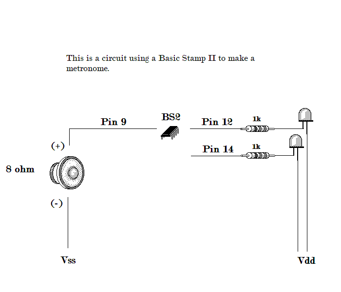
I wanted to make a metronome for myself to help with my guitar studies. I looked fairly well and found nothing in these forums that mentions how to use a BASIC Stamp II as a metronome.
So, I thought I'd try my hand at it, and came up with the attached circuit and code.
Please note three things:
1. I am new
2. I did do a metronome search before making this post.
3. I am aware that I should add a potentiometer so I could vary the speed of the 'clicks'
Take care.
▔▔▔▔▔▔▔▔▔▔▔▔▔▔▔▔▔▔▔▔▔▔▔▔
Deus tantum me iudicabit

Comments
▔▔▔▔▔▔▔▔▔▔▔▔▔▔▔▔▔▔▔▔▔▔▔▔
Dan Taylor
Thanks for the suggestion SRLM. However, as my initial post states, I am really new at this. If you could point me to an example or maybe post an example yourself, I would definitely appreciate it. I do have a Parallax LCD to play with, so I'd be eager to try it out.
Thanks again.
▔▔▔▔▔▔▔▔▔▔▔▔▔▔▔▔▔▔▔▔▔▔▔▔
Deus tantum me iudicabit
There are two LED's. One is RED and one is GREEN.
They alternate blinking each time there is a 'click' sound.
This adds a visual effect to compliment the audible sound of the metronome. It really does help.
▔▔▔▔▔▔▔▔▔▔▔▔▔▔▔▔▔▔▔▔▔▔▔▔
Deus tantum me iudicabit
I like metronomes. Good idea. Makes me want to build one, with maybe a motor so it has lights, sound, and a waving arm.
▔▔▔▔▔▔▔▔▔▔▔▔▔▔▔▔▔▔▔▔▔▔▔▔
When the going gets weird, the weird turn pro. -- HST
1uffakind.com/robots/povBitMapBuilder.php
1uffakind.com/robots/resistorLadder.php
Can I suggest adding a resistor (at least 220 Ohms) or capacitor (10uF ; observe polarity... positive to I/O pin) between pin9 and your 8 Ohm speaker?
Otherwise, you run the possibility of damaging your I/O pin.
Option #1:
With a 220 Ohm resistor, you limit the maximum current to the I/O pin to about 22mA.... otherwise, the 8 Ohm speaker is demanding about 625mA
Option #2
With a 10uF you have a 625mA surge that is very short lived between each transition from LOW to HIGH or HIGH to LOW.... When the pin is not in transition, the
current is virtually zero Amps.
Option #2, will provide the best volume.
▔▔▔▔▔▔▔▔▔▔▔▔▔▔▔▔▔▔▔▔▔▔▔▔
Beau Schwabe
IC Layout Engineer
Parallax, Inc.
▔▔▔▔▔▔▔▔▔▔▔▔▔▔▔▔▔▔▔▔▔▔▔▔
Deus tantum me iudicabit
Thanks for the heads-up. I'll try both to see the difference in volume.
Speaking of volume, how can I make the 'clicks' louder?
▔▔▔▔▔▔▔▔▔▔▔▔▔▔▔▔▔▔▔▔▔▔▔▔
Deus tantum me iudicabit
To make the clicks louder, you need to send your signal through an amplifier of some kind.... because of the nature of this project, a simple transistor amplifier would work.
You still need to take into consideration the current requirements. Using a transistor would basically allow you to go beyond the 25mA barrier of directly driving it from an I/O pin.
▔▔▔▔▔▔▔▔▔▔▔▔▔▔▔▔▔▔▔▔▔▔▔▔
Beau Schwabe
IC Layout Engineer
Parallax, Inc.
-Phil
▔▔▔▔▔▔▔▔▔▔▔▔▔▔▔▔▔▔▔▔▔▔▔▔
'Still some PropSTICK Kit bare PCBs left!
▔▔▔▔▔▔▔▔▔▔▔▔▔▔▔▔▔▔▔▔▔▔▔▔
Deus tantum me iudicabit
▔▔▔▔▔▔▔▔▔▔▔▔▔▔▔▔▔▔▔▔▔▔▔▔
Deus tantum me iudicabit
your post is off topic in this forum which is for Completed Projects only, not support. It is being moved to the BASIC Stamp Forum. Please post in the appropriate forum in the future.
▔▔▔▔▔▔▔▔▔▔▔▔▔▔▔▔▔▔▔▔▔▔▔▔
Chris Savage
Parallax Engineering
It uses a MOSFET transistor in a "common source" configuration. I used a 16-ohm speaker and got the best volume by connecting the high end of the speaker to Vin, rather than +5V. However, this may overdrive an 8-ohm speaker, so proceed with caution. The IRLZ34N is a "logic" MOSFET with a low gate threshold and is a real workhorse. No parts collection is complete without one. I also tried the circuit with a 2N7000 in a TO92 package. It worked fine with 5V (16-ohm speaker) but overheated at Vin, so I would not recommend it — especially with an 8-ohm speaker.
-Phil
P.S. Chris: Something really got screwed up here. I was working on this reply when you moved the thread, and I submitted it to the original forum after the thread was moved. My original reply (and the one that actually contains the referenced schematic) is now off in la-la land somewhere, unattached to any forum. I hope this doesn't mess up the forum software...
P.P.S.: Orphaned post deleted; image reposted here.
▔▔▔▔▔▔▔▔▔▔▔▔▔▔▔▔▔▔▔▔▔▔▔▔
'Still some PropSTICK Kit bare PCBs left!
Post Edited (Phil Pilgrim (PhiPi)) : 8/25/2008 10:55:05 PM GMT
Sorry, Chris. I do try to follow the forum rules.
My initial message was indeed a completed project. Other members then replied with suggestions to improve it.
I'll try not to let my future posts veer off course.
▔▔▔▔▔▔▔▔▔▔▔▔▔▔▔▔▔▔▔▔▔▔▔▔
Deus tantum me iudicabit
I have removed the orphan post.
Servello,
Your original message did not appear as a Completed Project. When it is, you should post it with an appropriate subject line and complete description. We just want the forums to be clean and easy for members to find things. If I am confused about a post, imagine what others will think.
By all means, once you’ve perfected your project feel free to post it, but please provide details including the subject. Take care.
P.S. - Interesting tagline...hopefully you don't feel we were judging you.·
▔▔▔▔▔▔▔▔▔▔▔▔▔▔▔▔▔▔▔▔▔▔▔▔
Chris Savage
Parallax Engineering
Post Edited (Chris Savage (Parallax)) : 8/25/2008 10:40:42 PM GMT
The basic premise is that one button will cycle through the available beats (with whatever step values you want to give it [noparse][[/noparse]1,5,10, etc]), while the second button will select that value. If you want to omit the second, then a hold on the first would do the same thing.
The LCD is just to display what beat value you are viewing/using, and possibly other information like button labels. See the documentation on how to use it.
Anyway, the psuedo code to select based on two buttons is like the following:
Display a BPM value
DO
Check button 1
If true (pressed) increment BPM and go back to begining
Check button 2
If true (pressed) begin metronome sequence with the current BPM
LOOP
Then, once you have the BPM, you can use a mathematical formula to relate the BPM to the correct length of the pause statements. Remember that if you have two lights (red and green) it will only really be effective for time signatures with two beats per measure, or some multiple thereof (4,6,8,10,12, etc.) If you try to use it with something like 3/4 time, then on one measure the green light will be the downbeat, on the next the red light will be the downbeat.
The presents an opportunity. You can use a single LED and toggle it, and display the count on the LCD. Of course, you'll have to give it the code to select between all the common time signatures, but the code is essentially the same as the BPM stuff.
Once you have it all setup and doing its metronome stuff, you can assign functions to the buttons like stop metronome (pauses until you start again), select new BPM, a dynamic higher or lower BPM, and new time signatures.
You should make a list of all the things that you want it to do. Don't omit anything, no matter how far off. Then just go down your list and realistically evauluate each option, and see how you can incorporate it. That way you'll have a tool that you can use for a long time, not just until you can buy one from the store.
Post Edited (SRLM) : 8/26/2008 4:31:32 AM GMT
Hehe. Good catch!
▔▔▔▔▔▔▔▔▔▔▔▔▔▔▔▔▔▔▔▔▔▔▔▔
Deus tantum me iudicabit
Thank you very much for taking the time to post such an informative reply. There is quite a bit there for me to go over. I think if I go over it a few times I may grasp what can be done.
Thanks again,
servello
▔▔▔▔▔▔▔▔▔▔▔▔▔▔▔▔▔▔▔▔▔▔▔▔
Deus tantum me iudicabit