

Measure external 24 presence without current flow?
 PDSAZ
Posts: 5
PDSAZ
Posts: 5
·Hi everyone,
I am still learning and getting up to speed and appreciate all the help here!
As you can tell I am a novice so thanks for your understanding.
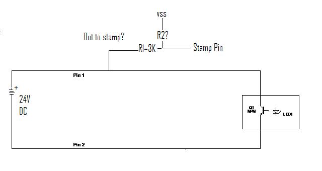
I have·a 24V DC external circuit.· I need to see if there is 24 volts present on this circuit with out shorting pins 1 and 2?·
in the attached drawing if Q1 is open.· How would I measure the voltage without closing the circuit to pin 2?
Basically it is just to tell me that 24v is present so I can light up an LED with the stamp indicating voltage presence.
I have looked a at a couple of circuits but, am scared of doing the wrong thing and killing my stamp.
Any suggestions?
Thanks all!
I am still learning and getting up to speed and appreciate all the help here!
As you can tell I am a novice so thanks for your understanding.
I have·a 24V DC external circuit.· I need to see if there is 24 volts present on this circuit with out shorting pins 1 and 2?·
in the attached drawing if Q1 is open.· How would I measure the voltage without closing the circuit to pin 2?
Basically it is just to tell me that 24v is present so I can light up an LED with the stamp indicating voltage presence.
I have looked a at a couple of circuits but, am scared of doing the wrong thing and killing my stamp.
Any suggestions?
Thanks all!
640 x 340 - 12K
Comments
Your·R2 should be about 750ohms with the 3K that gives you 4.8V at about 6mA so that will show a HIGH value on the stamp pin.
So connecting your + side of your external circuit through the resistor divider is correct.
If there is a chance the voltage can spike higher than 24V (motors are being driven, lighting strikes or static charge, you may wish to use a 4.8V zener or TVS diode from the stamp pin to ground as well and you have to make sure R2 is grounded and won't get disconnected (on a breadboard for example, oops) or you will have 24V going to your stamp pin!
Remember the grounds of both stamp and the external device must be common. (connected together)
▔▔▔▔▔▔▔▔▔▔▔▔▔▔▔▔▔▔▔▔▔▔▔▔
Think Inside the box first and if that doesn't work..
Re-arrange what's inside the box then...
Think outside the BOX!
Post Edited (metron9) : 8/15/2008 12:57:49 AM GMT
What you have in Photo >>>·24V measure >>> ·will not work because when you put power to pin 1 and pin 2· pins 4 and you·will have a short which will burn up your Optic Sensors
Here is all you need to do what you want to
look at photo below
Also look at this as well
What’s a Microcontroller?
Chapter #3: Digital Input - Pushbuttons · Page 71
Here is the Link to it
http://www.parallax.com/Portals/0/Downloads/docs/books/edu/Wamv2_2.pdf
In your case you just would not use the switch
·(your switch would be the Optic Sensor which you tell if you have 24 volts)·but every thing else would be the same
code wise
▔▔▔▔▔▔▔▔▔▔▔▔▔▔▔▔▔▔▔▔▔▔▔▔
··Thanks for any·
·
·
·
·
Sam
Post Edited (sam_sam_sam) : 8/15/2008 2:24:54 AM GMT
Thanks for the replies.· As I mentioned I am really new to this so I appreciate your patience.
Let me give some background.
There are 2 machines connected by cables.· machine A delivers parts to machine B.
Machine A will switch on 24V when it has parts ready to send to machine B.
machine B will close a switch (in this case the tranisitor but, could be a relay) when it is ready to receive parts.
When Machine A turns on 24V and machine B closes the circuit then parts are delivered from Machine A to Machine B.
I want to create a box that will show this in action I think the stamp is wells suited to do this. What·I need to know is·if their is 24V present without shorting pins 1 and 2.
I tried to attached another drawing that hopefully shows this better.· Metron/Sam does that change how I would go about it?
Sam - It looks like using the optocoupler that it would complete the circuit between pins 1 and 2 and cause the machine A to deliver parts as if the contacts on B were closed?
Thanks again for all the great help!
I would still·use what·I posted
Let me ask you something is there any reason why you are using 24 volt
If there is·NO reason why not use a 3 volt·Power supply·between the two
·
▔▔▔▔▔▔▔▔▔▔▔▔▔▔▔▔▔▔▔▔▔▔▔▔
··Thanks for any·
·
·
·
·
Sam
Post Edited (sam_sam_sam) : 8/15/2008 3:00:20 AM GMT
Thank You for catching that mistake i reworded it
▔▔▔▔▔▔▔▔▔▔▔▔▔▔▔▔▔▔▔▔▔▔▔▔
··Thanks for any·
·
·
·
·
Sam
Attached is the correct way to monitor the loop. To do so, you have to break the loop and insert your own optoisolator, which switches on when the loop is activated.
-Phil
Thanks again for the replies.· I will give your circuit a try.
Sam- The machine are already existing so I don't have the option to change it.
Phil - Thanks for catching my mistake on the polarity.· I was trying to draw it to show it conceptually and missed it.
Here is what I am trying to have when this is all said and done.
Machine A
My test box
Machine B where my test box·will do the following:
1.· Light an LED when both 24V is present and contactor on Machine B is closed.
2.· Light and LED when 24V is present regardless of state of machine B. without completing the circuit between A&B.
Thanks again.· Learning a ton from this forum!
-Phil
▔▔▔▔▔▔▔▔▔▔▔▔▔▔▔▔▔▔▔▔▔▔▔▔
'Still some PropSTICK Kit bare PCBs left!