

Support for RFID project
 makkia
Posts: 12
makkia
Posts: 12
Hi,
This is my first post here. I am Makkia from the middle east, I have recently found out about the BASIC stamp modules and the wide variety of applications possible using them.
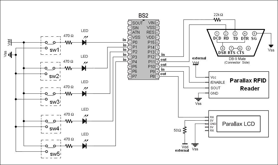
I have been doing some reasearch and reading the manuals and datasheets available for the BASIC stamp modules. Finally, I have designed a circuit for my senior project for college. Most of the project is software driven by a VB application that communicates with the BASIC Stamp 2 module for·input.
The·designed circuit (attached) was designed so that the BASIC Stamp II works as follows:
MAIN:
- wait for SERIN input from the Parallax RFID reader (wait until a tag is scanned).
- When input is availabe (all 11 bytes containing header and tag) then check for the status
of the five input switches.
- According to the status of the switches (which one is high and which one is low), send a
unique byte + the tag bytes to the PC via the serial connection on the RS-232 port --- If
the status of the switches is invalid, immediatly send an error string to the Parallax LCD
display and return to first line in main to wait for input from the RFID reader again
- wait for SERIN input from the PC, also via the serial connection on the RS-232 port --
The input should include a unique byte
- according to the byte recieved from the PC, send SEROUT string to the Parallax LCD
- return to first line in MAIN to wait for input from RFID reader again.
I did not write the BASIC Stamp 2· code yet as I want to make sure that the circuit is
valid and the expectations are actually possible.
I have a few questions regarding this circuit that I hope I could get answers for:
1) The 5 input LEDs draw out 7.2 mA of current each, resulting in a total 36 mA of sinking
current into the BASIC stamp, which according to the BASIC Stamp reference manual is ok.
However, I am not sure weather or not the serial connections with the Parallax LCD,
Parallax RFID reader and PC will draw/sink current from/into the BASIC stamp module that I
should account for. And if so, how much each?
2) the 50 ohm in the Vin of the Parallax LCD is because it says in the datasheet that for
backlight on, the LCD requires 100 mA.. is this how it should be connected to get the 100
mA?
3) In this circuit I am using the same RS-232 port for both input and output from/to the
PC, whereas a VB .NET application will be responsible for communicating with the BASIC
Stamp module. Is it ok to use the same communication port for both input and output to the
basic stamp? or do I need different ports?
4) Is it still going to work if I use a serial-to-USB adapter for the communications
between the BASIC Stamp module and the VB. NET application on the PC?
5) Clearly, I cannot use the Vdd regulated voltage from the BASIC Stamp module for the RFID
reader module and LCD (since most of the current will be used for the LEDs..). Can I use
another 12 VDC AC adapter connected to a +5V voltage regulator to get those two components
to work? and do I have to use one 12 VDC adapter or two of them (one for the LCD and one
for the RFID reader module) --- in the last case I would have three 12 VDC AC adapters, one
for the BASIC Stamp module, one for the RFID module and the last for the LCD.
6) Is there anything else wrong with the circuit that I should be aware of, and how do I
fix it
I hope I didn't do terrible mistakes!
This is my first post here. I am Makkia from the middle east, I have recently found out about the BASIC stamp modules and the wide variety of applications possible using them.
I have been doing some reasearch and reading the manuals and datasheets available for the BASIC stamp modules. Finally, I have designed a circuit for my senior project for college. Most of the project is software driven by a VB application that communicates with the BASIC Stamp 2 module for·input.
The·designed circuit (attached) was designed so that the BASIC Stamp II works as follows:
MAIN:
- wait for SERIN input from the Parallax RFID reader (wait until a tag is scanned).
- When input is availabe (all 11 bytes containing header and tag) then check for the status
of the five input switches.
- According to the status of the switches (which one is high and which one is low), send a
unique byte + the tag bytes to the PC via the serial connection on the RS-232 port --- If
the status of the switches is invalid, immediatly send an error string to the Parallax LCD
display and return to first line in main to wait for input from the RFID reader again
- wait for SERIN input from the PC, also via the serial connection on the RS-232 port --
The input should include a unique byte
- according to the byte recieved from the PC, send SEROUT string to the Parallax LCD
- return to first line in MAIN to wait for input from RFID reader again.
I did not write the BASIC Stamp 2· code yet as I want to make sure that the circuit is
valid and the expectations are actually possible.
I have a few questions regarding this circuit that I hope I could get answers for:
1) The 5 input LEDs draw out 7.2 mA of current each, resulting in a total 36 mA of sinking
current into the BASIC stamp, which according to the BASIC Stamp reference manual is ok.
However, I am not sure weather or not the serial connections with the Parallax LCD,
Parallax RFID reader and PC will draw/sink current from/into the BASIC stamp module that I
should account for. And if so, how much each?
2) the 50 ohm in the Vin of the Parallax LCD is because it says in the datasheet that for
backlight on, the LCD requires 100 mA.. is this how it should be connected to get the 100
mA?
3) In this circuit I am using the same RS-232 port for both input and output from/to the
PC, whereas a VB .NET application will be responsible for communicating with the BASIC
Stamp module. Is it ok to use the same communication port for both input and output to the
basic stamp? or do I need different ports?
4) Is it still going to work if I use a serial-to-USB adapter for the communications
between the BASIC Stamp module and the VB. NET application on the PC?
5) Clearly, I cannot use the Vdd regulated voltage from the BASIC Stamp module for the RFID
reader module and LCD (since most of the current will be used for the LEDs..). Can I use
another 12 VDC AC adapter connected to a +5V voltage regulator to get those two components
to work? and do I have to use one 12 VDC adapter or two of them (one for the LCD and one
for the RFID reader module) --- in the last case I would have three 12 VDC AC adapters, one
for the BASIC Stamp module, one for the RFID module and the last for the LCD.
6) Is there anything else wrong with the circuit that I should be aware of, and how do I
fix it
I hope I didn't do terrible mistakes!
941 x 558 - 69K
Comments
Welcome to the Parallax Forum
Take a look at this link and in the photo for the card reader you will see how
i mounted 5 volt regulator
http://forums.parallax.com/showthread.php?p=648149
Please explain what you want to do with the LEDs and the switches
1) The 5 input LEDs draw out 7.2 mA of current each, resulting in a total 36 MA of sinking
current into the BASIC stamp, which according to the BASIC Stamp reference manual is OK.
The LCD display dose not·need a resister but need a five regulator
However, I am not sure weather or not the serial connections with the Parallax LCD,
Parallax RFID reader and PC will draw/sink current from/into the BASIC stamp module that I
should account for. And if so, how much each?
▔▔▔▔▔▔▔▔▔▔▔▔▔▔▔▔▔▔▔▔▔▔▔▔
··Thanks for any·
·
·
·
·
Sam
This means that I would need two extra voltage regulators: one for the LCD and another for the RFID reader, right?
Also, about the switches, it's kind of complicated, but I'll try explaining it
This project was created to monitor the items inside a fridge, record the date each item was entered, the date the item was opened and monitor the expiry date.
although the RFID reader is connected to the PC via a serial port, it is not very efficient for the user to use dialog boxes everytime he/she enters an item in the fridge or removes an item. That's why I use the serial LCD and push button switches. I intend to label each switch with something like "get status" "report opened" and such.
An example of the functionality of this project:
·The user have taken a carton of milk out of the fridge and opened it but did not completely use it. He/she would have to press the "report opened" button then scan the item.
The BASIC stamp, when the item is scanned, checks for the button status to see what to do with the tag ID scanned.
since the "report opened" button is pressed, the BASIC stamp would send the tag ID along with a special identifier of this case to the VB application on the PC via the serial port.
The PC would recognize the tag ID and the special identifier,·and immediatly sets the status of this carton of milk to "inside the fridge" and "opened". -- such information is especially important since milk cartons expire within 3 days after opening, and within one month if not opened.
The PC responds to the BASIC stamp with a confirmation byte, the BASIC stamp reports this confirmation on the LCD display for the user. (note that if the tag was not registered into the system or something went wrong, the PC would respond with an error·byte, and cause the BASIC stamp to display the error on the LCD instead)
The rest of the switches will be used for the purposes of re-using the same tag for another item of the same type, when the old item is consumed.
This way, the user only needs to use the PC for controling this process when he/she purchases a new tag and wants to install it on the system or when he/she wants to use the tag ID for another type of food (ex. change from milk to eggs..)
I hope any of that made sense. Since I am still in the design phase I might will propably make more·changes in the procedure according to which·I find to be more convenient.
·IF YOU DO NOT USE THE BACK LIGHT
You could the (voltage regulator) for the LCD display board·on any Basic Stamp·Board··
·
This means that I would need two extra voltage regulators: one for the LCD and another for the RFID reader, right?
Other wise yes if you do not use the Back Light
▔▔▔▔▔▔▔▔▔▔▔▔▔▔▔▔▔▔▔▔▔▔▔▔
··Thanks for any·
·
·
·
·
Sam
Post Edited (sam_sam_sam) : 8/1/2008 11:37:46 AM GMT
The link for the project you made gave me great ideas for how I might write the code. Too bad your project got hit by lightining...
Anyway I will remove the resistance on the LCD, and use another voltage regulator for it since I will most likely use the backlight. I assume since no one else gave comments everything else is correct! (yay) and hope nothing burns when I assemble everything [noparse]:)[/noparse]
Here look at this will help you also
Chapter #3: Digital Input - Pushbuttons · Page 71
http://www.parallax.com/Portals/0/Downloads/docs/books/edu/Wamv2_2.pdf
Chapter #3: Digital Input - Pushbuttons · Page 77 will show you how to hook up a switch
Chapter #3: Digital Input - Pushbuttons · Page 81 will show you how to hook up a led
▔▔▔▔▔▔▔▔▔▔▔▔▔▔▔▔▔▔▔▔▔▔▔▔
··Thanks for any·
·
·
·
·
Sam
Post Edited (sam_sam_sam) : 8/1/2008 11:34:18 AM GMT
You're right, I was trying to get both the LED to work and the input to be HIGH when the switch is on, thanks a lot for the references, funny how this is where I went while trying to fix it [noparse]:D[/noparse]
Anyway, I think that a DPDT switch should fix the issue, new circuit is attached. And thanks for drawing my attention to this [noparse]:)[/noparse]
··When you switch from ON to OFF your inputs will FLOAT and you get changes in what state
·
When the switch is in between ON and OFF· the Input may·ON or OFF
Input will be in·(·No Man's Land it dose not know where it is this mean that wich ever routine is TRUE it will do)
......................>>>>> This will give you trouble
The trouble will be >>>··Let say that you have a routine that say when input 1 = ON
then do something what ever that is
and you have routine that say that when the input = OFF
then do something what ever that is
▔▔▔▔▔▔▔▔▔▔▔▔▔▔▔▔▔▔▔▔▔▔▔▔
··Thanks for any·
·
·
·
·
Sam
Post Edited (sam_sam_sam) : 8/1/2008 4:44:03 PM GMT
I adjusted the circuit as you advised, thanks again [noparse]:)[/noparse]
I got the part where the 10k ohm and ground should be connected at all times so that during the process of switching from ON to OFF the input·will not be floating. But·why does the 220 ohm need to be connected at all times as well?
You have it right now
Please explain this a Little bit better
·Just what you want·EACH switch's is to do
And are you going to use more than·ONE ·RFID Card
If you are going to use more than one card what do you want·EACH card to do·
Remember this if nothing eles that the Basic Stamp can
························ ONLY·DO ONE THING AT A TIME
- According to the status of the switches (which one is high and which one is low), send a
unique byte + the tag bytes to the PC via the serial connection on the RS-232 port --- If
the status of the switches is invalid, immediately send an error string to the Parallax LCD
display and return to first line in main to wait for input from the RFID reader again
Here are a few thing that can be done
You may also want to look at these project as well this might help you as well
·
This one thing i did with using two switch's
This part of a routine that i wrote in this project
Elapsed Clear Timer Board LCD Display
http://forums.parallax.com/showthread.php?p=737892
DO
DEBUG CLS
IF IN14 = 0 THEN
·· GOSUB Power_ON
ELSE
·· GOSUB Power_OFF
ENDIF
LOOP
Power_ON:
·DO WHILE IN15 = 0
GOSUB Display_Time
GOSUB Show_State_Power_ON
·LOOP
DO WHILE IN15 = 1
GOSUB Show_Time
GOSUB Show_State_Power_ON
LOOP
GOSUB Halt_clock
GOSUB Restart_clock
GOSUB Power_Restarts
GOSUB Power_ON
RETURN
Power_Off:
DO
·GOSUB Show_Time
·GOSUB Show_State_Power_OFF
·LOOP UNTIL IN15 = 1
DO
·GOSUB Display_Time
·GOSUB Halt_clock
·GOSUB Show_State_Power_OFF
LOOP UNTIL IN15 = 0
GOSUB Restart_clock
GOSUB Power_restarts:
GOTO Power_Off
RETURN
·
With each one of these projects i did·something diffrent with the card reader as you can see
On this one I have every card do a different routine
You may also want to look at this project as well this might help you as well
http://forums.parallax.com/showthread.php?p=595469
Soldering Station Timer Controller
Tag_Found:
ON tagNum GOSUB Routine0,· Routine1, Routine2, Routine3
On this i used Two Card Readers
http://forums.parallax.com/showthread.php?p=648149
Two Card Readers To A Gate Opener
· Reader1:
· #IF __No_SPRAM #THEN
··· SERIN RX1, T2400, 150, Reader2, [noparse][[/noparse]WAIT($0A), STR buf\10]········· ' wait for hdr + ID
· #ELSE
··· SERIN RX1, T2400, 150, Reader2, [noparse][[/noparse]WAIT($0A), SPSTR 10]
· #ENDIF
· HIGH Enable1······················································ ' deactivate reader - 1
· PAUSE 200························································· ' activate the reader - 1
·· GOTO Check_List
Reader2:
· #IF __No_SPRAM #THEN
··· SERIN RX2, T2400, 150, Reader1, [noparse][[/noparse]WAIT($0A), STR buf\10]········· ' wait for hdr + ID
··· #ELSE
··· SERIN RX2, T2400, 150, Reader1, [noparse][[/noparse]WAIT($0A), SPSTR 10]
· #ENDIF
· HIGH Enable2······················································ ' deactivate reader - 2
· PAUSE 200························································· ' activate the reader - 2
·GOTO Check_List
But·why does the 220 ohm need to be connected at all times as well
The reason the 220 ohm is it·LIMIT current to the input pin
The 220 Ω resistor is used in the pushbutton example circuits to protect the BASIC Stamp
I/O pin. Although it’s a good practice for prototyping·
▔▔▔▔▔▔▔▔▔▔▔▔▔▔▔▔▔▔▔▔▔▔▔▔
··Thanks for any·
·
·
·
·
Sam
Post Edited (sam_sam_sam) : 8/1/2008 6:38:12 PM GMT
sam,
The 220 Ω resistor is used in the pushbutton example circuits to protect the BASIC Stamp
I/O pin. Although it’s a good practice for prototyping·
isn't the 10k ohm resistor supposed to be enough to protect the BASIC stamp's I/O pin?
The system is connected to ONE RFID Reader module. However, There will be hundreds of RFID cards to be scanned.
The VB application will keep track of the tags. The only thing the basic stamp does is forward the tag ID and the input from the switches to the VB application.
Thanks a lot for the codes posted, it will help me figure out which is the best way to program the basic stamp to do its thing
·
isn't the 10k ohm resistor supposed to be enough to protect the BASIC Stamp's I/O pin?
No it is there to keep I/O pin from floating and to limit current from·vdd to vss
When You finish your project can you post· it the Completed Project Forum
Good Luck with your project
▔▔▔▔▔▔▔▔▔▔▔▔▔▔▔▔▔▔▔▔▔▔▔▔
··Thanks for any·
·
·
·
·
Sam
Post Edited (sam_sam_sam) : 8/1/2008 10:43:32 PM GMT
Indeed, it is my intention to post the full project on the completed projects forums.
I just want to spend as much time as it takes writing and testing the code for both the VB application and the BASIC stamp before I post anything. Thanks a lot for your help and advise
do I have to use one 12 VDC adapter or two of them (one for the LCD and one
for the RFID reader module) --- in the last case I would have three 12 VDC AC adapters, one
for the BASIC Stamp module, one for the RFID module and the last for the LCD.
·
One last thing
I re read your post and·I did not cover this part
If going to use a 12 VDC @ 1 Amp·AC adapter you will only need one but you will need to use a heat sink on your regulators or they will over heat
It would be better to use a 6 volt or a 7.2 volt AC adapter
If·You use a 12 VDC @ 1 Amp·AC adapter you·would waste power and give it up·as heat
If you use this set up·>>>>>·Two 12 VDC adapter·>>>>>>
Make sure that all of the components like the RFID Card Reader , LCD Display ,
Two 12 VDC adapter·and the Basic Stamp ·all share the same Vss Line
▔▔▔▔▔▔▔▔▔▔▔▔▔▔▔▔▔▔▔▔▔▔▔▔
··Thanks for any·
·
·
·
·
Sam
Post Edited (sam_sam_sam) : 8/2/2008 12:19:51 PM GMT