

Proto Board manual v1.2
 Dgswaner
Posts: 795
Dgswaner
Posts: 795
This may seem a bit nit picky, but I did make me do a double take and look at the schematic.
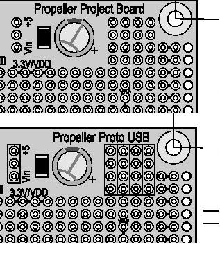
The Proto USB board has 4 pins for the servos blocked out. shouldn't it be 3? I thought for a second, that perhaps because there were 4 connectors that they were now USB. but the schematic does confirm that it's still the 3 pin servo connector.
.... Just thought I would mention it, that would have thrown me for a loop my first go around with the proto board.
▔▔▔▔▔▔▔▔▔▔▔▔▔▔▔▔▔▔▔▔▔▔▔▔
"A complex design is the sign of an inferior designer." - Jamie Hyneman, Myth Buster
DGSwaner
317 x 367 - 49K
Comments
.... just looked at the images on their site, the silk screen is how I would expect it to be, reading the schematic..... ok I'll stop nit picking.
▔▔▔▔▔▔▔▔▔▔▔▔▔▔▔▔▔▔▔▔▔▔▔▔
"A complex design is the sign of an inferior designer." - Jamie Hyneman, Myth Buster
DGSwaner