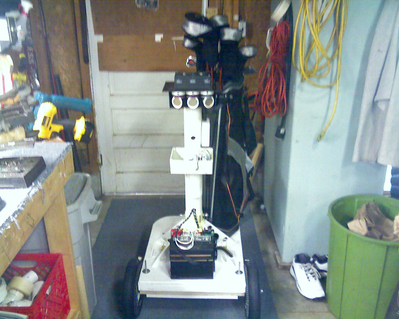
HB25 and 'free spinning'...
Is there a way to produce a dynamic brake or 'non' free spin using the HB25 motor controller from Parallax?
Deno
PS..Can someone tell me why my posts keep including the image photo when I do not attach it to the post.· This is the third time this image has posted with a post of mine.· I only posted this image one time with the orginal post...I am not talking abou the avatar to the left.
Post Edited (deno) : 7/26/2008 5:10:23 PM GMT


Comments
Er, ah, your robo caddy is working too well and it's following you?·
(Sorry, I couldn't resist
Very cool looking project, BTW!
- H
▔▔▔▔▔▔▔▔▔▔▔▔▔▔▔▔▔▔▔▔▔▔▔▔
Buzz Whirr Click Repeat
You MUST take care to only close the relay if and only if the HB-25 has stopped, otherwise the HB-25 will be feeding into a dead short.
In fact, if you use a C-form relay, use the NC contact in series with the HB-25 and the NO across the motor terminals. Then, the HB-25 will automatically be disconnected whenever the dynamic brake contact is closed.
··················· relay n/c
HB-25
|/|
Motor +
·································· |
·································· |
··································__
·····················Relay n/o __
·································· |
·································· |
HB-25___________________ Motor -
This has worked nicely on several ride-on cars I've worked on.
Cheers,
▔▔▔▔▔▔▔▔▔▔▔▔▔▔▔▔▔▔▔▔▔▔▔▔
Tom Sisk
http://www.siskconsult.com
·
Deno
PS Very good...CounterRoatingProps....
I would like to elaborate on what·stamptrol·has suggested, and this is a good safety mechanism, but I would wire it the other way so that the default position of the relay causes the motor to brake.· ... This in case of· a power loss, or other event.
There are several options in which you can expand this design.· The way that it is, it's known as a shunt brake because it literally places a short across the motor... remember when a motor spins it acts like a generator.· The voltage produced by the motor acts as a counter force to stop the motor, so shorting the terminals is an effective way to stop the motor.· It can also be a very abrupt quick braking method.· If you want a system that eases into braking a little more naturally then you can uses a Bridge rectifier and a MOSFET.· By applying PWM to the MOSFET you can control how much braking will be applied.· See Option #1 in the schematic.· Taking this·a bit further, there has been a little bit of discussion lately in the forum about regenerative braking.· To do this effectively you must do a power conversion from the power produced by the motor during free spin or braking which will always (not counting down-hill runs) be something less than your system supply voltage was able to provide.· So by sacrificing some of the current·produced from the motor during braking to increase the voltage ( <- A simple power inverter ) and then re-applying the voltage through a charge controller back into the battery system you can re-claim some of the energy so that it can·be used at a later time.· See Option #2 in the schematic.
▔▔▔▔▔▔▔▔▔▔▔▔▔▔▔▔▔▔▔▔▔▔▔▔
Beau Schwabe
IC Layout Engineer
Parallax, Inc.
Very simply, the brakes cannot possibly damage the motor controller because they motor controller in NOT connected during the braking process.
In most cases, this is a far better solution than reversing the motor. Braking is smoother and one can even have regenerative braking.
▔▔▔▔▔▔▔▔▔▔▔▔▔▔▔▔▔▔▔▔▔▔▔▔
It's sunny and warm here. It is always sunny and warm here.... (unless a typhoon blows through).
Tropically, G. Herzog [noparse][[/noparse] 黃鶴 ] in Taiwan