9 LED Resistor Value
All,
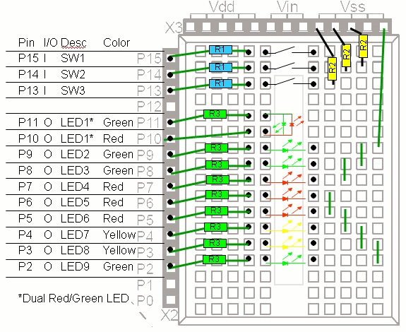
Attached is the basic schematic for an automotive project my son and I are doing this summer. We are using the 'Homework' BS2 board.
The first part of our project is to measure and control a go-kart engine.
In any case, the design uses 9 LEDs, and I don't want to draw too much current. It is OK if they are not very bright.
Question: What is a resistor value for the 9 LEDs that would not harm the chip? This is R3 in the attached schematic? Is there a calculator for such things? I am a novice with electronicc circuits.
Thanks!
- Bill


Comments
·····R = (5 - Vfwd) / .010
With a forward voltage of 1.75V, the appropriate resistor would be 330 ohms.
-Phil
▔▔▔▔▔▔▔▔▔▔▔▔▔▔▔▔▔▔▔▔▔▔▔▔
'Still some PropSTICK Kit bare PCBs left!
Thanks.
Thanks for the correction. I hadn't factored in the PIC's total rated load current. (I'm so used to driving LEDs at 20mA that 10mA seemed paltry!)
Bill,
If you're mixing similar green and red LEDs, you will probably need to drive the green ones a little harder than the red ones, if you want them to appear equally bright. (I don't use yellow ones often enough to remember where they generally fall brightness-wise.)
-Phil
▔▔▔▔▔▔▔▔▔▔▔▔▔▔▔▔▔▔▔▔▔▔▔▔
'Still some PropSTICK Kit bare PCBs left!
Why are there two formulas to solve the same problem?
R = (5 - Vfwd) / .010 ...the appropriate resistor would be 330 ohms
5V - 1.7V = 3.3V / 0.005A = 660 Ohms
Why twice the resistance vs the other formula?
Thanks!
LED formula: (Voltage in - LED voltage)/ LED current. As stated earlier the datasheet will provide LED Voltage and LED Current.
Chuck
Sorry: "drive harder" means "provide more current" (using a smaller resistor).
-Phil
▔▔▔▔▔▔▔▔▔▔▔▔▔▔▔▔▔▔▔▔▔▔▔▔
'Still some PropSTICK Kit bare PCBs left!
- Bill
http://www.parallax.com/Store/Components/IntegratedCircuits/InterfacingChips/tabid/613/CategoryID/78/List/0/SortField/0/Level/a/ProductID/211/Default.aspx
ULN2803A Darlington Array
Downloads:
N&V column "Silicon Steroids for the Stamp" #6 (.pdf)
·allanlane5
I think this sort of thing is the reason they make "Darlington Driver" chips...
I second this it would make thing a lot easier on you
▔▔▔▔▔▔▔▔▔▔▔▔▔▔▔▔▔▔▔▔▔▔▔▔
··Thanks for any·
·
·
·
·
Sam
The specification sheet has limits of power to each pin and each one byte port as a whole. If you go over those, the output stages burn up.
Buffer/Driver chips were made exactly for this application as they draw merely 1ma.
In many cases, with all the pins involved, the output pulses are limited to 1ma or 2ma. This can be done with a transistor [noparse][[/noparse]like the 2n2222] or driver ICs that output much more power to each·of its own·output·pins than was input. 1ma in can easily become 30ma out if needed.· Essentially these are just tiny power amplifiers.
If you are using all the pins for output, it is indeed better to have a 'driver' chip provide the power to the LEDs. But you don't need to use a specialized Darlington transistor arrangement, there are simple driver chips that maintain the 5 volt output with more millamps of power. Some invert and some do not. The 74ls06 aand 74ls07 might be appropriate.
Are these LEDs going to blink or stay steadily on? I have used 680 ohms on some blinking LEDS and couldn't see anything. You can use a 74ls07 and 220-330 ohms for good visibility. Save the UNL2308 for places where you need to jump to a higher voltage - like a 12volt relay coil or a stepper motor.
▔▔▔▔▔▔▔▔▔▔▔▔▔▔▔▔▔▔▔▔▔▔▔▔
It's sunny and warm here. It is always sunny and warm here.... (unless a typhoon blows through).
Tropically, G. Herzog [noparse][[/noparse] 黃鶴 ] in Taiwan
Post Edited (Kramer) : 7/23/2008 6:01:20 PM GMT
▔▔▔▔▔▔▔▔▔▔▔▔▔▔▔▔▔▔▔▔▔▔▔▔
It's sunny and warm here. It is always sunny and warm here.... (unless a typhoon blows through).
Tropically, G. Herzog [noparse][[/noparse] 黃鶴 ] in Taiwan
▔▔▔▔▔▔▔▔▔▔▔▔▔▔▔▔▔▔▔▔▔▔▔▔
·"If you build it, they will come."