

Detecting low voltage input
 computer guy
Posts: 1,113
computer guy
Posts: 1,113
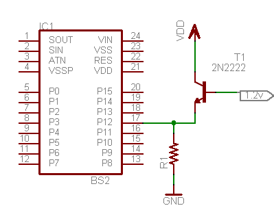
I have a switch that outputs 1.2v when pushed and 0v when released.
If I want the BS2 to detect the change I have to use a transistor right.
What value components would I use and will this circuit do the job.
Version1

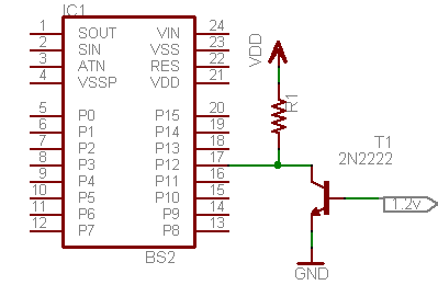
Version2

Thank you
▔▔▔▔▔▔▔▔▔▔▔▔▔▔▔▔▔▔▔▔▔▔▔▔
Building Blocks To The Propeller Chip A web site designed to help people who are new to the propeller chip.
Guitar Hero controller using the prop (WIP) --> HERE
If I want the BS2 to detect the change I have to use a transistor right.
What value components would I use and will this circuit do the job.
Version1
Version2
Thank you
▔▔▔▔▔▔▔▔▔▔▔▔▔▔▔▔▔▔▔▔▔▔▔▔
Building Blocks To The Propeller Chip A web site designed to help people who are new to the propeller chip.
Guitar Hero controller using the prop (WIP) --> HERE
399 x 304 - 4K
399 x 260 - 4K
Comments
Version 2 should work, but needs a resistor in series with the base lead to prevent the transistor from drawing too much current from the 1.2V input. 0.5mA is more than enough and a 1K resistor is about right. The collector resistor should be something like 1K for a 5mA collector current.
So this should work.
Version3
▔▔▔▔▔▔▔▔▔▔▔▔▔▔▔▔▔▔▔▔▔▔▔▔
Building Blocks To The Propeller Chip A web site designed to help people who are new to the propeller chip.
Guitar Hero controller using the prop (WIP) --> HERE
You may not even need a transistor at all... A simple voltage divider might work.
         15K       3.3K
5V >----/\/\---o---/\/\----< 0V to 1.2V input
               |
               o-----------> To I/O Pin
Since the I/O pin has a threshold of 1.4 Volts·.. When the input voltage is 0V, the voltage divider produces about 0.9 Volts at the input to the I/O Pin.· When the input voltage is 1.2V, the voltage divider produces about 1.88 Volts at the input to the I/O Pin.
▔▔▔▔▔▔▔▔▔▔▔▔▔▔▔▔▔▔▔▔▔▔▔▔
Beau Schwabe
IC Layout Engineer
Parallax, Inc.
▔▔▔▔▔▔▔▔▔▔▔▔▔▔▔▔▔▔▔▔▔▔▔▔
Thanks
NosePicker
·
You can use the standard voltage divider rule, but I prefer to use a derivative of that and find my current through the system first.· To do this you take the difference in voltage divided by the total amount of resistance.
·
In this example, the total amount of resistance will be fixed at 18.3K ( <-- 15K + 3.3K )
·
So when the input signal is 0V, the difference in voltage is 5V and the current is 273 micro Amps. ( <-- 5V / 18.3K)
Likewise, when the input signal is 1.2V, the difference in voltage is 3.8V and the current is 208 micro Amps. ( <-- 3.8V / 18.3K)
·
Now, the resistor of interest is the 3.3K ... If you take the current calculated above for a 0V input, and multiply it by the resistor value of 3.3K you get 0.901 Volts across that resistor.
·
Doing the same thing with the 1.2V input you get 0.68 Volts across that resistor·... But wait a minute! That's not the 1.88 Volts I mentioned earlier.· Take a closer look, you are now biasing the input with 1.2 Volts that gets "ADDED" to the 0.686 Volts.· 1.2V + 0.68V = 1.88V that the I/O "sees".
With those resistor values, I think that a 1V signal would still be enough to clear the 1.4V I/O threshold.· A 1 Volt input equates to·1.72V that the I/O would "see".
▔▔▔▔▔▔▔▔▔▔▔▔▔▔▔▔▔▔▔▔▔▔▔▔
Beau Schwabe
IC Layout Engineer
Parallax, Inc.
I think version 3 would work the best above all other ideas, but I would add a 10k resistor from the input·of the transistor to ground to prevent false trigger. I am assuming that when the switch is not pressed it is an open circuit and not zero volts. This open circuit would also prevent the resistor divider from working. If I were to use the resistor divider I would have·replaced the 3.3k with a 1N4148 assuming the input is at ground potential when open and not floating.
▔▔▔▔▔▔▔▔▔▔▔▔▔▔▔▔▔▔▔▔▔▔▔▔
D. A. Wreski
▔▔▔▔▔▔▔▔▔▔▔▔▔▔▔▔▔▔▔▔▔▔▔▔
Building Blocks To The Propeller Chip A web site designed to help people who are new to the propeller chip.
Guitar Hero controller using the prop (WIP) --> HERE