

Propcorder - a general purpose Propeller powered LCD/button interface idea
 Timothy D. Swieter
Posts: 1,613
Timothy D. Swieter
Posts: 1,613
In another thread I started talking about a general purpose LCD/button user interface product idea for Brilldea.· I have pieced together more thoughts about this product and I wanted to seek advice from those visiting the Sandbox.
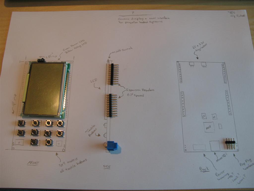
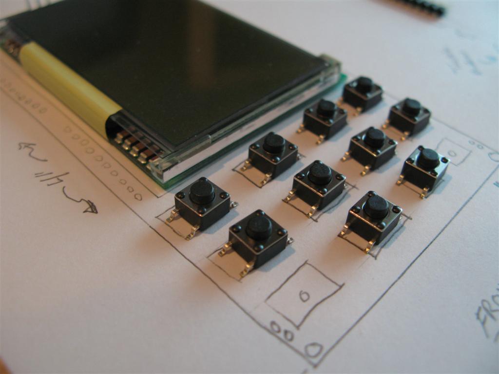
The intent of the product is to provide a platform upon which other applications can be built.· The platform at a minimum would include an LCD, a configurable button arrangement, voltage regulation and expansion headers.· I attached a picture of a "prototype"·sketch of the device with some of the potential components overlaid on the sketch.·
Possible uses for this device include:
A little more detail.· This is all preliminary and your feedback is welcomed to improve this spec.· Remember this product is trying to be a platform for add-on boards and not a kitchen sink to have all possible interfaces because those can be added with the add-on boards.
I really like the expansion header idea and I need to draw a couple more layout to get the layout right.· Brilldea would offer proto boards or maybe specific cards for different applications.· Again, the add-on cards could span one group of expansion headers or both groups.· Maybe I will have a means to have a larger PCB that is the same size as the Propcorder.· I need to be careful of component heights for the components chosen.
For a little while I thought about using a capacitive touch button arrangement on the Propcorder (like your iPOD).· I am shying away from it now though because the IC would complicate the design slightly and may also complicate the software.· Also, in the future maybe Brilldea can offer a case for this design.· If I did that, the cap sense buttons would have some constraints to what materials the case can be made out of and dimensions around and near the buttons.
I need to do more design and research before pricing can be considered.· I also need to review if full or partial assemblies would be sold or if it would be a kit·with "some assembly required".
What are your thoughts?· What should be added or taken away?· Is the Propcorder a good name?· What applications would you use the device in?
▔▔▔▔▔▔▔▔▔▔▔▔▔▔▔▔▔▔▔▔▔▔▔▔
Timothy D. Swieter, E.I.
www.brilldea.com·- Prop Blade, LED Painter, RGB LEDs, uOLED-IOC
www.sxmicro.com - a blog·exploring the SX micro
www.tdswieter.com
The intent of the product is to provide a platform upon which other applications can be built.· The platform at a minimum would include an LCD, a configurable button arrangement, voltage regulation and expansion headers.· I attached a picture of a "prototype"·sketch of the device with some of the potential components overlaid on the sketch.·
Possible uses for this device include:
- thermostat (another thread on thermostats·inspired me to finally get off the fence with this idea)
- home automation interface
- handheld test equipment
- industrial system interface
- Lighting system controller
- remote sensor display and data logging
- handheld propeller video games
- robotics
- Tricorder unit!
A little more detail.· This is all preliminary and your feedback is welcomed to improve this spec.· Remember this product is trying to be a platform for add-on boards and not a kitchen sink to have all possible interfaces because those can be added with the add-on boards.
- A two layer PCB approximately 4.0" x 2.25".· The PCB would have small mounting holes in the four corners.
- Power comes in at the bottom of the PCB.· I have not decided on the footprint for this part yet.· Maybe there would be multiple footprints like one for a DC barrel jack, one for a blue terminal block (like in the picture) and one for two wires.
- On-board voltage regulation for 5V and 3.3V.· I want to investigate regulators to use.· On a previous product, the Prop Blade, I used the LM1086 which is what the Propeller Protoboard uses.· I would like to consider different regulators so that the incoming voltage can be 12V DC or maybe even 24V DC.· Any suggestions on·specific regulator products to look at?·
- An on/off switch at the top of the PCB.· This switch could be populated or it could be left off and a jumper installed for always on applications.· An LED near the power switch would indicate power is on.·
- A 128 x 96 monochrome LCD with four grey scale levels.· The LCD would have·a white·backlight.· Here is a video on YouTube of the LCD on a test bench.· Watch the video in high resolution, it is a much better representation.
- A button array that can handle up to 12 tactile buttons.· The PCB could be populated with only the buttons needed.· If your application only uses two buttons, then only populate two buttons.· If your applications wants one button on the left and three on the right, then populate that way as well.
- An led at the top of the PCB (near the on/off switch) that is a general purpose LED.
- QFP Propeller with a 5 MHz. crystal.· Two eeproms, or at least a spot for up to two eeproms with at least one populated for the boot eeprom.·
- Programmed via the Prop Plug.
- MicroSD slot - maybe.· This would be a nice addition, but I am not sold on the idea yet.
- Two groups of 0.1" spaced headers.· Maybe 10 pins each or 12 pins each side.· These are the expansion·headers for attaching protoboard or perf board or custom PCBs.· The expansion headers could have one large PCB installed on it or two smaller PCBs.· The headers are shown in the photo, but it is not crystal clear how to use them since I didn't draw add-on cards.· Each header group would have the unused I/O as well as the other I/O such as the I2C bus.· Also, the 3.3V, 5V and Incoming power to the PCB could be made available on the expansion headers.·
I really like the expansion header idea and I need to draw a couple more layout to get the layout right.· Brilldea would offer proto boards or maybe specific cards for different applications.· Again, the add-on cards could span one group of expansion headers or both groups.· Maybe I will have a means to have a larger PCB that is the same size as the Propcorder.· I need to be careful of component heights for the components chosen.
For a little while I thought about using a capacitive touch button arrangement on the Propcorder (like your iPOD).· I am shying away from it now though because the IC would complicate the design slightly and may also complicate the software.· Also, in the future maybe Brilldea can offer a case for this design.· If I did that, the cap sense buttons would have some constraints to what materials the case can be made out of and dimensions around and near the buttons.
I need to do more design and research before pricing can be considered.· I also need to review if full or partial assemblies would be sold or if it would be a kit·with "some assembly required".
What are your thoughts?· What should be added or taken away?· Is the Propcorder a good name?· What applications would you use the device in?
▔▔▔▔▔▔▔▔▔▔▔▔▔▔▔▔▔▔▔▔▔▔▔▔
Timothy D. Swieter, E.I.
www.brilldea.com·- Prop Blade, LED Painter, RGB LEDs, uOLED-IOC
www.sxmicro.com - a blog·exploring the SX micro
www.tdswieter.com
1024 x 768 - 53K
1024 x 768 - 63K
Comments
▔▔▔▔▔▔▔▔▔▔▔▔▔▔▔▔▔▔▔▔▔▔▔▔
Timothy D. Swieter, E.I.
www.brilldea.com·- Prop Blade, LED Painter, RGB LEDs, uOLED-IOC
www.sxmicro.com - a blog·exploring the SX micro
www.tdswieter.com
John Abshier
It may also be worth considering having different types button layouts, which I know wouldn't be economical selling this as a hobbiest board, but unless I'm wrong, I can see some people using your platform to make a product and then ask for 100 of them at a pop.· If you had different button platforms that people could purchase and snap in (maybe a numeric pad, or some scroll bars, or 4 push buttons) and you could produce them inexpensively where you are, it could give you more selling options in terms of accessorizing.
I was looking at that infinity thermostat I have to see what I liked about its UI.· One nice thing about it is that it has 4 side buttons on it that are at each corner of the lcd.· This is very nice, becasue sometimes the system will ask for a specific input, and have the options displayed on the lcd next to the appropriate buttons.· I think this would be nice for any application, not just a t-stat.· I also noticed that my tstat LCD is black/white like yours and has shades of grey which they use nicely.· I think your LCD will do well.· The link below doesn't show the bottom panel that is opened up, there is more config buttons there.
http://www.residential.carrier.com/products/controls/infinity.shtml
Note, I'm referencing a tstat because its the only wall mounted device I know of, other than my alarm panel, and its UI isn't that nice.
· Maybe bluetooth as an option ?
· Then you could have the tstats talk to each other, and to the furnace wirelessly.
· Just an idea...
Bean.
▔▔▔▔▔▔▔▔▔▔▔▔▔▔▔▔▔▔▔▔▔▔▔▔
- - - - - - - - - - - - - - - - - - - - - - - - - - - - - - -
"A government big enough to give you everything you want, is big enough to take away everything you·have."·· Thomas Jefferson
"It is our choices, Harry, that show what we truly are, far more than our abilities."·Dumbledore from Harry Potter
www.iElectronicDesigns.com
·
▔▔▔▔▔▔▔▔▔▔▔▔▔▔▔▔▔▔▔▔▔▔▔▔
- Stephen
As you stated in another thread, the ability to flip the display between portrait and landscape.· Maybe by using different display pin headers and reading a jumper?
A group of pads for off-board keypads, especially for interfacing a telephone type keypad.· I would also like at to be able to add at least sixteen buttons, in a 4x4 electrical matrix.· Maybe consider 20 buttons max? (4x5 array?)
On-board multi-channel ADC chip, suggest at least four input channels.
User-populated area for MAX232 type chip?· Would allow for RS-232 or RS-485 communications.
Also, base the size of the display and the button layout on an off-the-shelf enclosure.
A good looking enclosure is what separates a one-off prototype and a successful kit IMHO.
Power and Expansion headers.
- I want to sketch out a couple ideas for power and layout.· I was thinking that all power busses would be on the expansion header (input power, 5V, 3.3V), not just jumper selectable power.· Maybe I am misunderstanding what you are suggesting.
On-board radio.User Interface.
Other I/O and part requests.
Keep the ideas and feedback coming.
▔▔▔▔▔▔▔▔▔▔▔▔▔▔▔▔▔▔▔▔▔▔▔▔
Timothy D. Swieter, E.I.
www.brilldea.com·- Prop Blade, LED Painter, RGB LEDs, uOLED-IOC
www.sxmicro.com - a blog·exploring the SX micro
www.tdswieter.com
Infinity Control user guide.
▔▔▔▔▔▔▔▔▔▔▔▔▔▔▔▔▔▔▔▔▔▔▔▔
Timothy D. Swieter, E.I.
www.brilldea.com·- Prop Blade, LED Painter, RGB LEDs, uOLED-IOC
www.sxmicro.com - a blog·exploring the SX micro
www.tdswieter.com
This thermostat is a very good
I am a A/C Tech by trade
A few though that·I would like to have if i where going to built one I will keep watching this post to see what you come up with
# 1 There need filter reminder when to change it base on hour of running for cooling and heat (If done right would also know how much of the time you unit is running in a month)
#2 Thermostat Zones names are a good idea· I·wish that there was one on the market for home use this would where you have a Thermostat in every
room in your house
#3 Adaptive mode where it Will learn how long it take to cool down you house
when you need it be cool down when you come from work ( it would nice if you can tweak as well
#4· Home, Away, Sleep, Weekend, Vacation timers
#5 Fan speed control this is a nice idea for home A\C unit
You can get· these units but they are only for 15 sheer and up
what is need is fan control for unit that are under 15 sheer you could choose
Cooling one of two speeds·High·or Med speed·base on suction line temp an RH %·level
Fan speed would Med·or Low if air handler has Three speed fan or not
Heat one of two speed base on temp on the heat strip
Heat one of two speed base on suction line temp and room temp
#6 Have a out side damper option where between Spring and Summer You could have outside air only base on side temp and RH % level
▔▔▔▔▔▔▔▔▔▔▔▔▔▔▔▔▔▔▔▔▔▔▔▔
··Thanks for any·
·
·
·
·
Sam
Post Edited (sam_sam_sam) : 7/14/2008 1:22:16 AM GMT
This would do two things. One, it would solve your portrait/landscape issue, and you could have a couple of different layouts (if you want). Or, just have a generic one for now and consider more later. Or... Supply a generic plug in board where people could lay out their own buttons.
The problem with this solution is that your basic board would have to fit within the footprint of the basic LCD. The positive is that in some cases, someone may prefer the smaller panel where there is just the LCD and 4 control buttons (as in a home control unit of some sort). I could see that, if I had an LCD in each bedroom, I could see where I could accomplish most things, bump up temp, see outside temp etc with just the 4 buttons.
I like your idea of plugable button board. I can see that it would lend itself to the users being able to get what they want. On the other hand though it might complicate the design and at a minimum the cost of PCB tooling and designing seperate boards would go up. The idea is good and it would make the tricorder idea more general purpose than it is now.
Hmmmm....
Is there a generic enough interface that could be designed that would make it appeal to the masses? I always like the idea of a scroll wheel/jog dial and a couple buttons. I really like the iPOD like interface and I started a UI a while ago on the uOLED-PROP-96 that simulated this but I never finished that software. Something similar could be done on this complete with capacitive sensing scroll wheel or a mechanical one. The capacitive sense has its advantages and disadvantages though.
The design shown in the picture can't get any taller without exceeding my current license on EAGLE for PCB size. The board could get wider, but then it might feel funny in the hand for those potential hand applications.
Maybe I am trying to tossout too wide of a net by trying to make the design expandable and appealing to many. The goal of this product design is to provide a platform for a user interface consisting of an LCD and buttons and maybe an LED or two. The platform should lend itself to be as open, expandable and available for whatever the application may be.
Right now I am going to stay focused on the LCD, button, interaction design issue and see what other ideas I come up with.
▔▔▔▔▔▔▔▔▔▔▔▔▔▔▔▔▔▔▔▔▔▔▔▔
Timothy D. Swieter, E.I.
www.brilldea.com·- Prop Blade, LED Painter, RGB LEDs, uOLED-IOC
www.sxmicro.com - a blog·exploring the SX micro
www.tdswieter.com
Iteration is a very, very important part of design - especially when it involves design for others. Tweaking and improving can be done only with feedback from using and trying it out.
▔▔▔▔▔▔▔▔▔▔▔▔▔▔▔▔▔▔▔▔▔▔▔▔
Timothy D. Swieter, E.I.
www.brilldea.com·- Prop Blade, LED Painter, RGB LEDs, uOLED-IOC
www.sxmicro.com - a blog·exploring the SX micro
www.tdswieter.com
The idea is still to provide a generic user interface in hardware and software and then add-on boards could be attached to the back of the device.· I am trying to limit the I/O usage on the user interface to allow for the max number of I/O on the expandable headers on back.·
▔▔▔▔▔▔▔▔▔▔▔▔▔▔▔▔▔▔▔▔▔▔▔▔
Timothy D. Swieter, E.I.
www.brilldea.com·- Prop Blade, LED Painter, RGB LEDs, uOLED-IOC, eProto fo SunSPOT, BitScope
www.sxmicro.com - a blog·exploring the SX micro
www.tdswieter.com
Like this example - www.youtube.com/watch?v=7kzIHMpOt20
That would give it an ultra-cool look and feel. for the jog wheel you have sketched out, you could use leds set in a circle.
You may need a slave processor so that you aren't using too much of the Propellers resources (both cogs and IO lines) you run the display/input system.
▔▔▔▔▔▔▔▔▔▔▔▔▔▔▔▔▔▔▔▔▔▔▔▔
Brian
uController.com - home of SpinStudio - the modular Development system for the Propeller
PropNIC - Add ethernet ability to your Propeller! PropJoy - Plug in a joystick and play some games!
SD card Adapter - mass storage for the masses Audio/Video adapter add composite video and sound to your Proto Board
▔▔▔▔▔▔▔▔▔▔▔▔▔▔▔▔▔▔▔▔▔▔▔▔
Searider
The center scroll wheel is a capacitive sensor.· There is a metal dome button in the center and then three on each side of the scroll wheel.· I am considering have the six outside buttons be backlight metal dome.· Those six metal domes would have a hole punched in the center.· The PCB would also have a hole an a SMT LED would be mounted on the back of the PCB.· Then the button can be light up.· In the drawing actually drew an LED next to the button, but I like the backlight idea better.
▔▔▔▔▔▔▔▔▔▔▔▔▔▔▔▔▔▔▔▔▔▔▔▔
Timothy D. Swieter, E.I.
www.brilldea.com·- Prop Blade, LED Painter, RGB LEDs, uOLED-IOC, eProto fo SunSPOT, BitScope
www.sxmicro.com - a blog·exploring the SX micro
www.tdswieter.com
this is a nice idea - go with the Tricoder idea! I mean, look at those wheels under the tricorder's front flap. They are wheels aren't they? Don't know how you'd hook pots up to them... or maybe use an optical encoder. A few less buttons and more wheels. Have several screen resolution options. And I'd have a case, like the tricoders, or some enclosure with only a three or four connectors: USB, XLR (3 or 5 pin), power in, and ???
thanks for sharing this project.
- Howard in Florida
▔▔▔▔▔▔▔▔▔▔▔▔▔▔▔▔▔▔▔▔▔▔▔▔
Buzz Whirr Click Repeat
In time I may be able to provide a case or so. Tooling and production in China isn't too bad, but is still an investment that would need to be pay off.
▔▔▔▔▔▔▔▔▔▔▔▔▔▔▔▔▔▔▔▔▔▔▔▔
Timothy D. Swieter, E.I.
www.brilldea.com·- Prop Blade, LED Painter, RGB LEDs, uOLED-IOC, eProto fo SunSPOT, BitScope
www.sxmicro.com - a blog·exploring the SX micro
www.tdswieter.com