

Dallas DS2413 sample code
 Kas
Posts: 19
Kas
Posts: 19
Hi,
The Dallas DS2413 is a new Dual addressable switch using the 1wire protocol
The 2 channels can be assigned as Digital Input or Digital Output
This chip supersedes the DS2405 single switch
(For reference, the sample code for DS2450 quad ADC is here: http://forums.parallax.com/showthread.php?p=732559)
A search on DS2413 brings no hits
This demo program
·- reads the button state on PIOB
·- sets a LED accordingly on PIOA
'
' {$STAMP BS2p}
' {$PBASIC 2.5}
'1-wire Dallas DS2413 Dual addressable switch
'This program reads PIOB state (button) and set PIOA LED accordingly
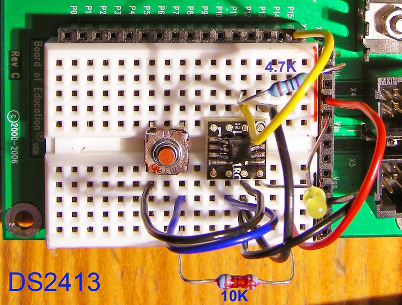
'4.7K pullup on OWpin
'button with 10k·pullup on DS2413 PIOB (pin 4)
'LED on DS2413 PIOA (pin 6)
OWpin··········· CON·· 15························· ' 1-Wire bus
OW_FERst········ CON·· %0001······················ ' Front-End Reset
OW_BERst········ CON·· %0010······················ ' Back-End Reset
OW_BitMode······ CON·· %0100
OW_HighSpd······ CON·· %1000
PIOR············ CON·· $F5························ ' PIO access read
PIOW············ CON·· $5A························ ' PIO access write
ReadROM········· CON·· $33························ ' read ID, serial num, CRC
MatchROM········ CON·· $55························ ' look for specific device
SkipROM········· CON·· $CC
ON1············· CON·· %11111101·················· ' output 1 ON
ON2············· CON·· %11111110·················· ' output 2 ON
ONF2············ CON·· %00000001·················· ' output 2 OFF
OFF12··········· CON·· %11111111·················· ' output 1 & 2 OFF
MSEC············ CON·· 100························ ' pause
command········· VAR·· Byte······················· ' data sent to DS2413
info············ VAR·· Byte······················· ' data received from DS2413
ButtonState····· VAR·· info.BIT2·················· ' Button state
i··············· VAR·· Nib
'
[noparse][[/noparse] Main Code ]
'
DEBUG CLS
DO
· GOSUB Read_data············································ ' read DS2413 DIO-A state
· IF ButtonState = 0 THEN
··· command = ON2
··· ' command = info & ON2
··· GOSUB Write_Data········································· ' write DS2413 DIO-B state
··· DEBUG HOME, "ON ", CR
· ELSE
··· command = OFF12
··· GOSUB Write_Data········································· ' write DS2413 DIO-B state
··· DEBUG HOME, "OFF", CR
· ENDIF
· PAUSE MSEC
LOOP
'
[noparse][[/noparse] Subroutines ]
'
Write_Data:
· info=0
· OWOUT OWpin, OW_FERst, [noparse][[/noparse]SkipROM, PIOW, command , ~command]· ' send commande
· OWIN OWpin, 0, [noparse][[/noparse]info]
· IF info = $AA THEN········································· ' get confirmation byte
··· DEBUG "confirmation... ", "ACK: ", HEX info
· ELSEIF info = $FF THEN
··· DEBUG "confirmation... ", "NAK: ", HEX info
· ELSE
··· DEBUG "confirmation... ", "???: ", HEX info
· ENDIF
· info=0
· OWIN OWpin, OW_BERst, [noparse][[/noparse]info]······························· ' get PIO status
· DEBUG "··· Status: ", BIN4 info, CR
RETURN
Read_data:
· info=0
· OWOUT OWpin, OW_FERst, [noparse][[/noparse]SkipROM, PIOR]····················· ' send PIO ACCESS READ
· OWIN OWpin, OW_BERst, [noparse][[/noparse]info]······························· ' get PIO status
RETURN
'
Circuit implementation is straightforward see picture;
DS2413 was soldered on a SOIC to DIP converter
Enjoy·
Yves
Post Edited (Kas) : 6/28/2008 6:01:24 AM GMT
The Dallas DS2413 is a new Dual addressable switch using the 1wire protocol
The 2 channels can be assigned as Digital Input or Digital Output
This chip supersedes the DS2405 single switch
(For reference, the sample code for DS2450 quad ADC is here: http://forums.parallax.com/showthread.php?p=732559)
A search on DS2413 brings no hits
This demo program
·- reads the button state on PIOB
·- sets a LED accordingly on PIOA
'
' {$STAMP BS2p}
' {$PBASIC 2.5}
'1-wire Dallas DS2413 Dual addressable switch
'This program reads PIOB state (button) and set PIOA LED accordingly
'4.7K pullup on OWpin
'button with 10k·pullup on DS2413 PIOB (pin 4)
'LED on DS2413 PIOA (pin 6)
OWpin··········· CON·· 15························· ' 1-Wire bus
OW_FERst········ CON·· %0001······················ ' Front-End Reset
OW_BERst········ CON·· %0010······················ ' Back-End Reset
OW_BitMode······ CON·· %0100
OW_HighSpd······ CON·· %1000
PIOR············ CON·· $F5························ ' PIO access read
PIOW············ CON·· $5A························ ' PIO access write
ReadROM········· CON·· $33························ ' read ID, serial num, CRC
MatchROM········ CON·· $55························ ' look for specific device
SkipROM········· CON·· $CC
ON1············· CON·· %11111101·················· ' output 1 ON
ON2············· CON·· %11111110·················· ' output 2 ON
ONF2············ CON·· %00000001·················· ' output 2 OFF
OFF12··········· CON·· %11111111·················· ' output 1 & 2 OFF
MSEC············ CON·· 100························ ' pause
command········· VAR·· Byte······················· ' data sent to DS2413
info············ VAR·· Byte······················· ' data received from DS2413
ButtonState····· VAR·· info.BIT2·················· ' Button state
i··············· VAR·· Nib
'
[noparse][[/noparse] Main Code ]
'
DEBUG CLS
DO
· GOSUB Read_data············································ ' read DS2413 DIO-A state
· IF ButtonState = 0 THEN
··· command = ON2
··· ' command = info & ON2
··· GOSUB Write_Data········································· ' write DS2413 DIO-B state
··· DEBUG HOME, "ON ", CR
· ELSE
··· command = OFF12
··· GOSUB Write_Data········································· ' write DS2413 DIO-B state
··· DEBUG HOME, "OFF", CR
· ENDIF
· PAUSE MSEC
LOOP
'
[noparse][[/noparse] Subroutines ]
'
Write_Data:
· info=0
· OWOUT OWpin, OW_FERst, [noparse][[/noparse]SkipROM, PIOW, command , ~command]· ' send commande
· OWIN OWpin, 0, [noparse][[/noparse]info]
· IF info = $AA THEN········································· ' get confirmation byte
··· DEBUG "confirmation... ", "ACK: ", HEX info
· ELSEIF info = $FF THEN
··· DEBUG "confirmation... ", "NAK: ", HEX info
· ELSE
··· DEBUG "confirmation... ", "???: ", HEX info
· ENDIF
· info=0
· OWIN OWpin, OW_BERst, [noparse][[/noparse]info]······························· ' get PIO status
· DEBUG "··· Status: ", BIN4 info, CR
RETURN
Read_data:
· info=0
· OWOUT OWpin, OW_FERst, [noparse][[/noparse]SkipROM, PIOR]····················· ' send PIO ACCESS READ
· OWIN OWpin, OW_BERst, [noparse][[/noparse]info]······························· ' get PIO status
RETURN
'
Circuit implementation is straightforward see picture;
DS2413 was soldered on a SOIC to DIP converter
Enjoy·
Yves
Post Edited (Kas) : 6/28/2008 6:01:24 AM GMT
790 x 600 - 157K