Shop OBEX P1 Docs P2 Docs Learn Events
Prop High(er) voltage interface — Parallax Forums

Prop High(er) voltage interface

PhilldapillPhilldapill Posts: 1,283
edited 2008-06-28 15:12 in Propeller 1
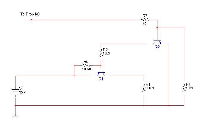
This is problem a simple and unsophisticated solution, but I need to control the flow of current from a solar panel to a load. The current will be under PWM control from the propeller, but I'm afraid of a bad wiring design and frying the prop. I would use a P-mosfet, but don't want to wait for the order. I have a TON of some high-freq, 7A, 80V PNP transistors that I've found to have a pretty low Vce saturation voltage. Pulling 600mA through it, I only get a 0.125V drop. Anyway, I'm trying to use these transistors to control the current, but I'm afraid of some kind of voltage spike or something frying a pin. Oh, the PNP is a 2SA2023, and the NPN is a 2N3904.

Any problems/suggestions?

Oh, a basic electrical question... If I want to move 1 coulomb through a 100 ohm resistor, won't it take more energy to move it the faster it goes? i.e. current rate of 1A for 1 second, vs. 2A for 1/2 second?

1A*1A*100ohms*1second = 100 Joules
2A*2A*100ohms*0.5seconds = 200 Joules?

The reason I ask, is I'm thinking that if I'm using PWM to control current flow, then higher current and lower duty cycle would have higher losses, right?
689 x 430 - 4K

Comments

  • Graham StablerGraham Stabler Posts: 2,507
    edited 2008-06-27 22:43
    Power is I^2R so yes more current means more power and over time energy. For a given power to be transfered it is better to use higher voltage and lower current to reduce I^2R losses but that is not always practical/possible.

    But what is this 100ohms?

    Graham
  • Mike GreenMike Green Posts: 23,101
    edited 2008-06-27 22:49
    In an ideal circuit, higher current for shorter time should be the same as lower current for longer time.· We live in a less than ideal world though.· Transistors don't switch infinitely quickly.· Wires have some inductance and capacitance to each other, etc.· There's usually a "sweet spot" in a PWM scheme where the losses are at a minimum.· Where you'll find it will depend on the parts you use, the wiring, any inductance and capacitance in the components, etc.
  • PhilldapillPhilldapill Posts: 1,283
    edited 2008-06-27 23:23
    I take it you guys don't have any problems with the circuit attached and it should work well for switching power fairly efficiently, and NOT frying the prop?
  • Mike GreenMike Green Posts: 23,101
    edited 2008-06-28 00:51
    The 10K resistor in the base lead of Q1 may be too low. That depends on the gain of Q1 and how much current you want to switch. You need to have enough base current to saturate the transistor. You'll have to get that from the datasheet. Other than that, the circuit looks ok. You can always fry the Prop in other ways. You'll be dealing with high currents. Be careful about ground loops
  • Ken PetersonKen Peterson Posts: 806
    edited 2008-06-28 02:51
    @Phil: Your math is correct. Power goes with the square of the current, but for a given power energy is proportional to time. Therefore, if you double the current and cut the duration in half, you double the energy dissipated in your 100 ohm load.

    Think of it another way. In order to double the current through that resistor, you have to double the voltage (V=IR). So to move the coulomb in half the time, you need twice the voltage and twice the current which equals four times the power (P=VI).

    Bottom line: Haste makes waste roll.gif

    ▔▔▔▔▔▔▔▔▔▔▔▔▔▔▔▔▔▔▔▔▔▔▔▔


    Post Edited (Ken Peterson) : 6/28/2008 2:57:12 AM GMT
  • PhilldapillPhilldapill Posts: 1,283
    edited 2008-06-28 02:57
    Thanks Ken. The math makes sense, and thinking about the increased voltage drop across the resistor x the charge moved, makes sense. It was just a passing thought as I was writing, but at the time it didn't make sense. Do you see any flaws in the circuit, other than the 10K (R2) resistor that might need to be lower? Like I said, I'm using these PNP transistors instead of a mosfet because they have a very low Vce drop and will dissipate about 0.1W at 0.75A. I plan on putting a few of these in parallel with individual base resistors, of course.
  • hinvhinv Posts: 1,253
    edited 2008-06-28 03:33
    Might I ask what the purpose of the circuit is?
  • Ken PetersonKen Peterson Posts: 806
    edited 2008-06-28 03:35
    Per your diagram, nothing jumps out at me as something that is potentially damaging to the Prop. Just make sure that all high current paths have low inductance (no open loops and return path close to supply path) because fast switching coupled with high currents and inductance leads to high voltage transients.

    What type of load do you have? Is it purely resistive as your diagram shows?

    ▔▔▔▔▔▔▔▔▔▔▔▔▔▔▔▔▔▔▔▔▔▔▔▔
  • scottascotta Posts: 168
    edited 2008-06-28 03:39
    Philldapill,

    Add a small cap in parallel to R3 (say .01uf). This will speed up the switching time.
  • Ken PetersonKen Peterson Posts: 806
    edited 2008-06-28 03:46
    Wouldn't hurt

    ▔▔▔▔▔▔▔▔▔▔▔▔▔▔▔▔▔▔▔▔▔▔▔▔
  • PhilldapillPhilldapill Posts: 1,283
    edited 2008-06-28 03:47
    Oh, nice scotta. That makes sense. When the prop pin goes high, the cap acts as a short, bypassing the 1K resistor for the shortest risetime possible. Then it quickly charges and becomes an open so there is normal current flow through R3. Same thing in reverse for the pin going low, eh. I suppose I should decrease the cap size as my freq goes up?
  • PhilldapillPhilldapill Posts: 1,283
    edited 2008-06-28 03:53
    scotta, shouldn't I still have at least a 100 ohm resistor in series with the cap with both the 100ohm and cap in parallel with the 1K resistor? I'm worried about the high current discharge from the cap as the pin goes low.
  • Ken PetersonKen Peterson Posts: 806
    edited 2008-06-28 04:03
    I'm guessing 0.01uF shouldn't cause a problem for the Prop.

    I = C dv/dt

    with that capacitance, you can charge the cap to 3.3V at 40ma in 1 microsecond.

    ▔▔▔▔▔▔▔▔▔▔▔▔▔▔▔▔▔▔▔▔▔▔▔▔


    Post Edited (Ken Peterson) : 6/28/2008 4:12:14 AM GMT
  • PhilldapillPhilldapill Posts: 1,283
    edited 2008-06-28 04:05
    Good to know. I've fried a few of these(8 and counting) and am a little bit leary of doing it again.
  • scottascotta Posts: 168
    edited 2008-06-28 15:12
    Probably not a bad idea to calculate it before hand.

    I would use an opto-isolator for sure. They are pretty
    slow but very in-expensive.
Sign In or Register to comment.