Shop OBEX P1 Docs P2 Docs Learn Events
ac voltage checker via Caps and RCTIME — Parallax Forums

ac voltage checker via Caps and RCTIME

Bobb FwedBobb Fwed Posts: 1,119
edited 2008-06-24 16:41 in General Discussion
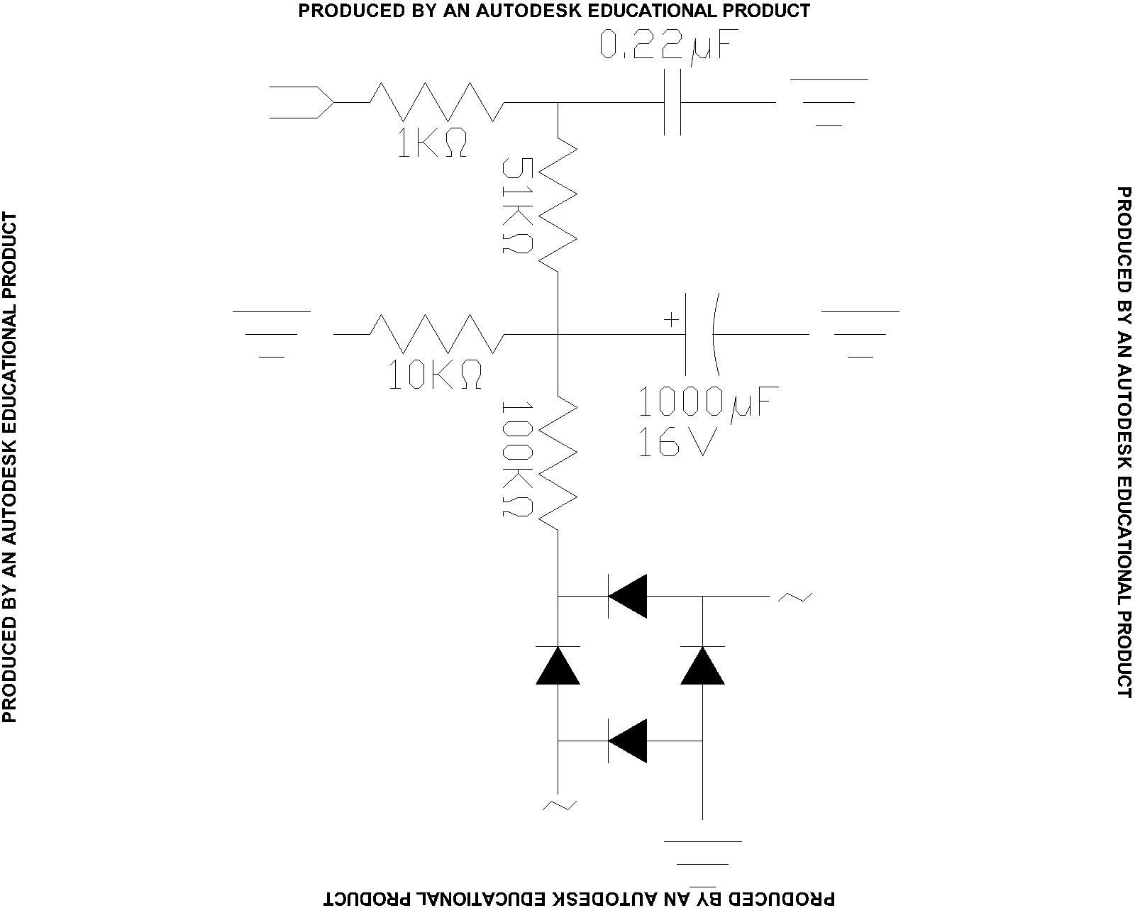
I am trying to wire up an AC voltage checker. I've wired a DC checker and it works great, but I keep blowing fuses (on a variable voltage box) when I try the same idea with an AC setup. Attached is my diagram. Please tell me what I am doing wrong. I'm starting out the voltage at 6VAC, and even that is blowing the 3A fuse.

I may be a little excessive on resistors, but the way I had it wired was everything above the 1000µF cap (not including) was how I measure the DC voltage. Now I added a voltage divider (10K-ohm and 100K-ohm) with a 1000µF cap to stabilize the AC; and finally the bridge rectifier (don't know the symbol for that -- that's the 4 diodes at the bottom).

What am I doing wrong?
1600 x 1280 - 97K

Comments

  • Mike GreenMike Green Posts: 23,101
    edited 2008-06-23 22:48
    For some reason, I can't read your diagram.· Try producing it again and look at it before you post it.

    If you're blowing fuses, you must have a short circuit somewhere.
  • Bobb FwedBobb Fwed Posts: 1,119
    edited 2008-06-23 22:51
    Hm. I can see it just fine.
    That's what I was thinking (a short), but i don't know where...there are high-ohm resistors between everything.
    1600 x 1280 - 97K
  • PJAllenPJAllen Banned Posts: 5,065
    edited 2008-06-23 22:53
    Maybe your bridge (FWB) is kaput?
  • Bobb FwedBobb Fwed Posts: 1,119
    edited 2008-06-23 23:01
    tried new bridge rectifier...still doesn't work.
    I got up to 8.4V this time.
    I made sure the variable AC voltage box (thingy) wasn't frying itself. I ran a power supply off it at 120V.

    can someone else wire up something similar? it seems like it should work....
  • Mike GreenMike Green Posts: 23,101
    edited 2008-06-23 23:05
    What kind of variable voltage AC box thingy are you using? Often, they're just an autotransformer, not isolated from the AC line. Very very dangerous if so. If it is isolated, but one output terminal is grounded, it will cause problems if the two grounds are connected.
  • Bobb FwedBobb Fwed Posts: 1,119
    edited 2008-06-23 23:12
    a Staco 3PN501: www.interstatesurplus.com/products.asp?cat=26
    It's kinda old, but we have used it often and never had a problem.
    Note: it is rated for 5A, but we only have 3A fuses (should work fine....same voltage).
  • PJAllenPJAllen Banned Posts: 5,065
    edited 2008-06-23 23:12
    How about a picture of your set-up?
    ·
  • Bobb FwedBobb Fwed Posts: 1,119
    edited 2008-06-23 23:33
    trying to get a picture....all the camera phones around here suck...and no real cameras. Maybe if I can't get this one phone to work, I can bring my Nikon tomorrow.

    Edit: Man camera phones suck! I'll work on getting a real photo tomorrow some time (during work hours here in PST).
  • Bobb FwedBobb Fwed Posts: 1,119
    edited 2008-06-23 23:40
    Does everyone at least think it should work (based on the diagram)? Has anyone tried this type of thing before?
  • Phil Pilgrim (PhiPi)Phil Pilgrim (PhiPi) Posts: 23,514
    edited 2008-06-24 00:10
    Please reread Mike's post. The Staco unit is an autotransformer, not an isolated transformer. You will need an isolation transformer after the Staco unit to perform your tests safely and without destroying equipment, blowing fuses, or electrocuting yourself.

    -Phil
  • Bobb FwedBobb Fwed Posts: 1,119
    edited 2008-06-24 15:26
    OK, safety aside. I am wanting to implement this to be able to plug directly into a wall socket; I need to prototype it before, so I don't think wall sockets are isolated. I have photos now of my setup, and am trying to down size them to upload to here.
  • Bobb FwedBobb Fwed Posts: 1,119
    edited 2008-06-24 15:40
    Images are attached. Sorry, they came out a little blurry.

    Post Edited (Bobb Fwed) : 6/24/2008 3:45:19 PM GMT
    3008 x 2000 - 180K
    3008 x 2000 - 191K
  • Phil Pilgrim (PhiPi)Phil Pilgrim (PhiPi) Posts: 23,514
    edited 2008-06-24 15:58
    Without an isolation transformer, you simply can't have external, AC-operated equipment, like a PC, connected to your test setup. The reason is that logic ground will be connected back through your PC, through chassis ground, thence to mains ground, back to your breaker box, where it connects to AC Neutral. When the AC Hot lead goes negative, it shorts through your bridge rectifier to AC Neutral through that convoluted ground circuit, blowing out the fuse in your autotransformer. Get it? And I'm not on board with "safety aside", either, even though the foolhardy days of my youth saw me do worse, I'm sure. Get an isolation transformer, and use it, until you've got your setup fully working, debugged, and ready to install in a double-insulated housing.

    -Phil
  • Bobb FwedBobb Fwed Posts: 1,119
    edited 2008-06-24 16:10
    OK, that makes a little more sense. And I didn't mean to ignore safety ... more so I meant something, uh more safe than that.
  • Beau SchwabeBeau Schwabe Posts: 6,568
    edited 2008-06-24 16:41
    For a simple low power AC isolation you can use two back to back transformers. I typically prefer using a transformer with a CT (Center Tap) and utilize that connection as well (<- optional). Just make sure that you are using two transformers that are identical to each other so that they have equal loading characteristics and you don't overload them beyond what they are rated for.

    But as others have suggested, SAFETY is your number one priority and should never be ignored!

    ▔▔▔▔▔▔▔▔▔▔▔▔▔▔▔▔▔▔▔▔▔▔▔▔
    Beau Schwabe

    IC Layout Engineer
    Parallax, Inc.
    1203 x 527 - 144K
Sign In or Register to comment.