

Can someone check this board layout for me?
 MarkS
Posts: 342
MarkS
Posts: 342
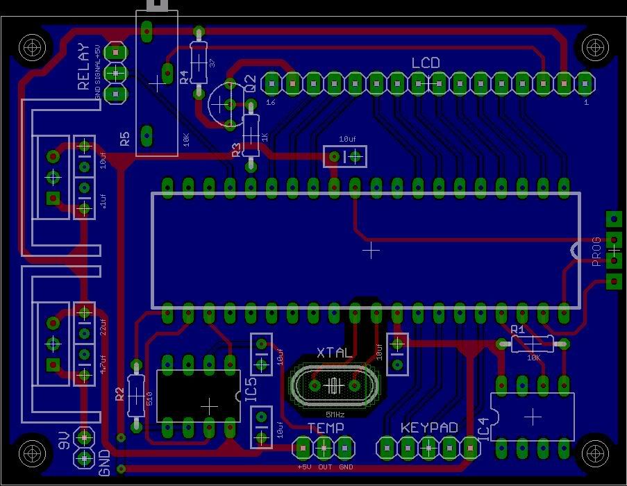
This is a digital temperature controller. It uses a Prop. IC4 is the EEPROM and IC5 is a LTC1298 12-bit ADC. The circuit has been prototyped and it works, but I want to make sure that the board layout is free of any general layout errors. I know that the circuit is correct, but this would be the first "real" board I've completed. I'm not too certain about things like power traces crossing signal traces and trace lengths (the 3.3v power trace concerns me, but I'm not sure why...). I've made sure that there are no 90° bends in any traces and all traces are as short as possible. Power traces are wider than signal traces, all bypass caps are close to their respective components, only two vias (which I'd like to get rid of) and most traces are in one layer whenever possible.
The board is small, only 3" x 2.25".
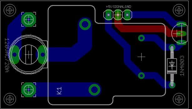
Also, do to the AC current that the relay will be switching, I put the relay on a separate board. The relay will be turning the guts of a ceramic heater on and off. I'm less concerned about noise and more concerned that the AC traces will stand up to the potential load. AC scares the Smile out of me!
This board is tiny, only 2" x 1.15".
I've uploaded the board and schematic files. You'll notice a lack of values in the schematics. I smashed the components and then deleted the values and names on the boards and then when I realized what I've done, I cannot bring them back. The values shown on the boards, ordinary text, are correct as per my prototype.
Any help will be appreciated.
Thanks,
Mark
The board is small, only 3" x 2.25".
Also, do to the AC current that the relay will be switching, I put the relay on a separate board. The relay will be turning the guts of a ceramic heater on and off. I'm less concerned about noise and more concerned that the AC traces will stand up to the potential load. AC scares the Smile out of me!
This board is tiny, only 2" x 1.15".
I've uploaded the board and schematic files. You'll notice a lack of values in the schematics. I smashed the components and then deleted the values and names on the boards and then when I realized what I've done, I cannot bring them back. The values shown on the boards, ordinary text, are correct as per my prototype.
Any help will be appreciated.
Thanks,
Mark

Comments
A couple of things I have picked up on as I did similar things with my first board:-
You could do with some in-line current limiting resistors on the LCD interface.
Whilst in normal circumstances it won't be a problem, my experience is that if you issue the wrong command and set the lcd to 'output' mode you can damage the Prop.
Is the ground plane on the top or bottom layer?
My personal preference is for it to be the top layer as it is then closer to the components.
I would also connect a track between the two 3v3 supply rails to the Prop.
Good luck!
Regards,
Coley
▔▔▔▔▔▔▔▔▔▔▔▔▔▔▔▔▔▔▔▔▔▔▔▔
PropGFX Forums - The home of the Hybrid Development System and PropGFX Lite
Leon
▔▔▔▔▔▔▔▔▔▔▔▔▔▔▔▔▔▔▔▔▔▔▔▔
Amateur radio callsign: G1HSM
Suzuki SV1000S motorcycle
OK, I can change the caps to 100nf, but the ADC has a decoupling cap already and it is the 10uf that the data sheet specifies. I do not believe that I've ever seen anyone place one on the EEPROM. Not that it's a bad idea, it is just usually omitted. The relay has a diode across the coil already.
Post Edited (MarkS) : 6/21/2008 5:53:17 PM GMT
I like to decouple each supply pin with 100 n. Small ceramic capacitors have much better high-frequency performance than 10 uF ones.
Leon
▔▔▔▔▔▔▔▔▔▔▔▔▔▔▔▔▔▔▔▔▔▔▔▔
Amateur radio callsign: G1HSM
Suzuki SV1000S motorcycle
Post Edited (Leon) : 6/21/2008 6:14:10 PM GMT
I wont dispute you on that point.
The ADC data sheet does specify a 10uf cap though. Should I disregard that and use a 100nf instead? It seems to be working fine with the 10uf.
I still have some questions. When you smash a part on the board and then delete the name and/or value, how do you bring them back?
Also, any word on the relay board. Specifically, the AC traces?
That new layout looks better.
Leon
▔▔▔▔▔▔▔▔▔▔▔▔▔▔▔▔▔▔▔▔▔▔▔▔
Amateur radio callsign: G1HSM
Suzuki SV1000S motorcycle