Optical encoder problem.
Along with my Submarine project me and a friend are also working on an electric vehicle using old metal scraps, sprockets, batteries, and an electric wheel chair I picked up for $25
I have two questions but I’ll just ask one then ask the other one later. ·
I bought this video game steering wheel for a $1 thought it would be easy to interface with a BS2 and have it control the wheel chair motors but I’m having a bit of trouble.
Before I even get to the electronics part of this I hit a wall, at least to my knowledge.
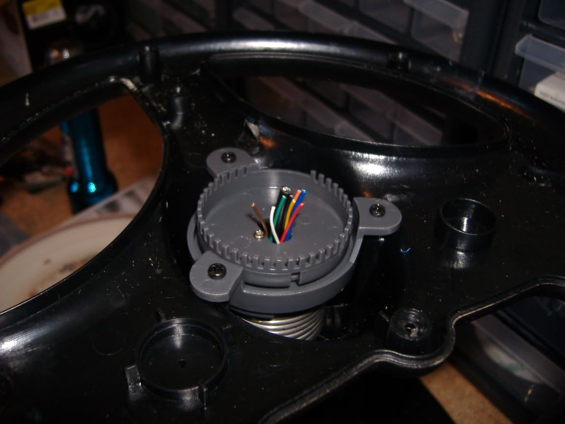
There is a plastic wheel (pictured below) for the most part it looks like any other optical encoders I’ve read about. Has “teeth” that block the light and openings that let it pass through. And a large opening on the far side so you know when you have turned all the way to either side.
In this case the encoder turns with the wheel and this plastic teethed piece stays in place. My·· question is how does it (my program/me) know if I’m turning left or right since either direction would act in the same way?
·
I simply can’t figure out how it knows.

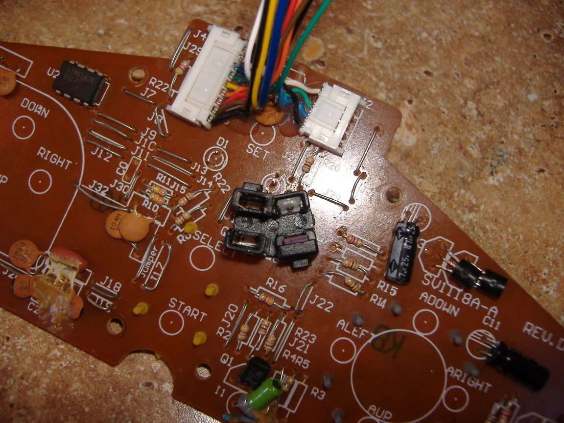
Near the middle tords the right is the optical encoder.

·
▔▔▔▔▔▔▔▔▔▔▔▔▔▔▔▔▔▔▔▔▔▔▔▔
There are no Undo buttons in life.
I have two questions but I’ll just ask one then ask the other one later. ·
I bought this video game steering wheel for a $1 thought it would be easy to interface with a BS2 and have it control the wheel chair motors but I’m having a bit of trouble.
Before I even get to the electronics part of this I hit a wall, at least to my knowledge.
There is a plastic wheel (pictured below) for the most part it looks like any other optical encoders I’ve read about. Has “teeth” that block the light and openings that let it pass through. And a large opening on the far side so you know when you have turned all the way to either side.
In this case the encoder turns with the wheel and this plastic teethed piece stays in place. My·· question is how does it (my program/me) know if I’m turning left or right since either direction would act in the same way?
·
I simply can’t figure out how it knows.

Near the middle tords the right is the optical encoder.

·
▔▔▔▔▔▔▔▔▔▔▔▔▔▔▔▔▔▔▔▔▔▔▔▔
There are no Undo buttons in life.


Comments
▔▔▔▔▔▔▔▔▔▔▔▔▔▔▔▔▔▔▔▔▔▔▔▔
·"If you build it, they will come."
▔▔▔▔▔▔▔▔▔▔▔▔▔▔▔▔▔▔▔▔▔▔▔▔
Chris Savage
Parallax Tech Support
That Wiki makes since but I just don’t see how mine can do that. So your saying that what I thought was a IR LED and a Photo transistor is actual a IR LED and two photo transistor, and by knowing which one breaks the beam first you can tell direction. That would make a tone of since and be sort of easy to program. But I have a felling it’s a bit different because they were talking about square waves, do I have to send it a signal. Or is it just like having two photo transistors like on the Boe-Bot.
Thanks for the help but I’m still a tad bit lost.
▔▔▔▔▔▔▔▔▔▔▔▔▔▔▔▔▔▔▔▔▔▔▔▔
There are no Undo buttons in life.
It appears to me that there is only one LED / transistor set, even though there is a place for a second set.
So given this information is it possible that the three pin thing across from the IR LED is in fact two separate receivers spaced apart a bit. I don’t know if that’s even possible but just thronging it out there. I’ll try to trace the paths and see where it all connects.
▔▔▔▔▔▔▔▔▔▔▔▔▔▔▔▔▔▔▔▔▔▔▔▔
There are no Undo buttons in life.
-Phil
▔▔▔▔▔▔▔▔▔▔▔▔▔▔▔▔▔▔▔▔▔▔▔▔
There are no Undo buttons in life.
-Phil
▔▔▔▔▔▔▔▔▔▔▔▔▔▔▔▔▔▔▔▔▔▔▔▔
There are no Undo buttons in life.
-Phil
▔▔▔▔▔▔▔▔▔▔▔▔▔▔▔▔▔▔▔▔▔▔▔▔
There are no Undo buttons in life.
The pulldowns are there to force the signal pins to ground when there's little or no current being sourced by the detector in its "off" state. Otherwise, the pins could float in an indeterminate state or remain high from the slightest leakage current.
-Phil
So now I should be able to hook it up to the breadboard and program it. I was setting here just logically thinking about what a chart would look like for CW and CCW and I got a chart that looks just like the one Erco showed me here http://en.wikipedia.org/wiki/Rotary_encoder#Incremental_rotary_encoder
I’ve got to go out of town today but when I get back I’ll work a bit more on the programming. I don’t know why but I’m vary excited to have figured this out, maybe it’s because I’ve always logically knew how sensors like this work but I’ve never known how to use them in a circuit.
A bit of topic but I know you guys will help; I understand the purpose of a resister in general it limits the amount of current that can flow through it. I know how to find the value in ohms and I’ve used them a lot in different circuits that others designed. But aside from driving an LED I have no idea when to use them or what value in ohms/watts to use. Just like in the case here I know I need a 10K to pull it down to ground but that’s only form being told that and I don’t know why its 10k. So if anyone could just give me a quick lowdown on the subject or send me a link. That ·would be so helpful.
Well anyway like I said I’ve got to leave town in a bit, I might be able to take it in the car and program it there idk.
▔▔▔▔▔▔▔▔▔▔▔▔▔▔▔▔▔▔▔▔▔▔▔▔
There are no Undo buttons in life.
Since I’m using this for an electric car I’m going to want more than just CW and CCW dada I also need to know how far it has gone in either direction.
So this is my idea, when the wheel is at rest I get | A = 0 B = 0 |that’s perfect. So I can recognize this as a starting point. And have some variable set at 180 ·now say it turns one step ··| A = 1 B = 0 | A = 1 B = 1 | I know it went CW one notch so I could subtract 1 from the 180 to get 179 and keep subtracting if its following the CW pattern. And of course if it starts following a CCW pattern ill start adding to 179.
Then when I get around to interfacing the “gas” petal I can use this value along with the “gas” peddle numbers to determine how fast to turn. Not just turn at the same speed as the pedal.
This works so perfectly in my head but how do I do it. It must be very simple just I don’t know how.
I need to store or remember the state of both switches then when the sate of either one changes I need to determine did it go CW or CCW and then erase the current stored value and replace it with the current value so it’s up to date for the next turn.
Then like I said once I know if it went CW or CCW id just add or subtract from the 180 var.
Any suggestions or terms I need to look up actually there syntaxes right? Well here is the program I have right now just to test the states.··
' {$STAMP BS2}
' {$PBASIC 2.5}

x VAR Byte
y VAR Byte
DO
x = IN6
y = IN1

DEBUG BIN1  x
DEBUG BIN1  y
PAUSE 500
LOOP
▔▔▔▔▔▔▔▔▔▔▔▔▔▔▔▔▔▔▔▔▔▔▔▔
There are no Undo buttons in life.
Still looking for some ideas on the encoder, Thanks
▔▔▔▔▔▔▔▔▔▔▔▔▔▔▔▔▔▔▔▔▔▔▔▔
There are no Undo buttons in life.
▔▔▔▔▔▔▔▔▔▔▔▔▔▔▔▔▔▔▔▔▔▔▔▔
There are no Undo buttons in life.
▔▔▔▔▔▔▔▔▔▔▔▔▔▔▔▔▔▔▔▔▔▔▔▔
There are no Undo buttons in life.
The whole chip could be dead.
How did you have this wired? What board are you using?
▔▔▔▔▔▔▔▔▔▔▔▔▔▔▔▔▔▔▔▔▔▔▔▔
There are no Undo buttons in life.