

Analog to Digital >5V
 Bobb Fwed
Posts: 1,119
Bobb Fwed
Posts: 1,119
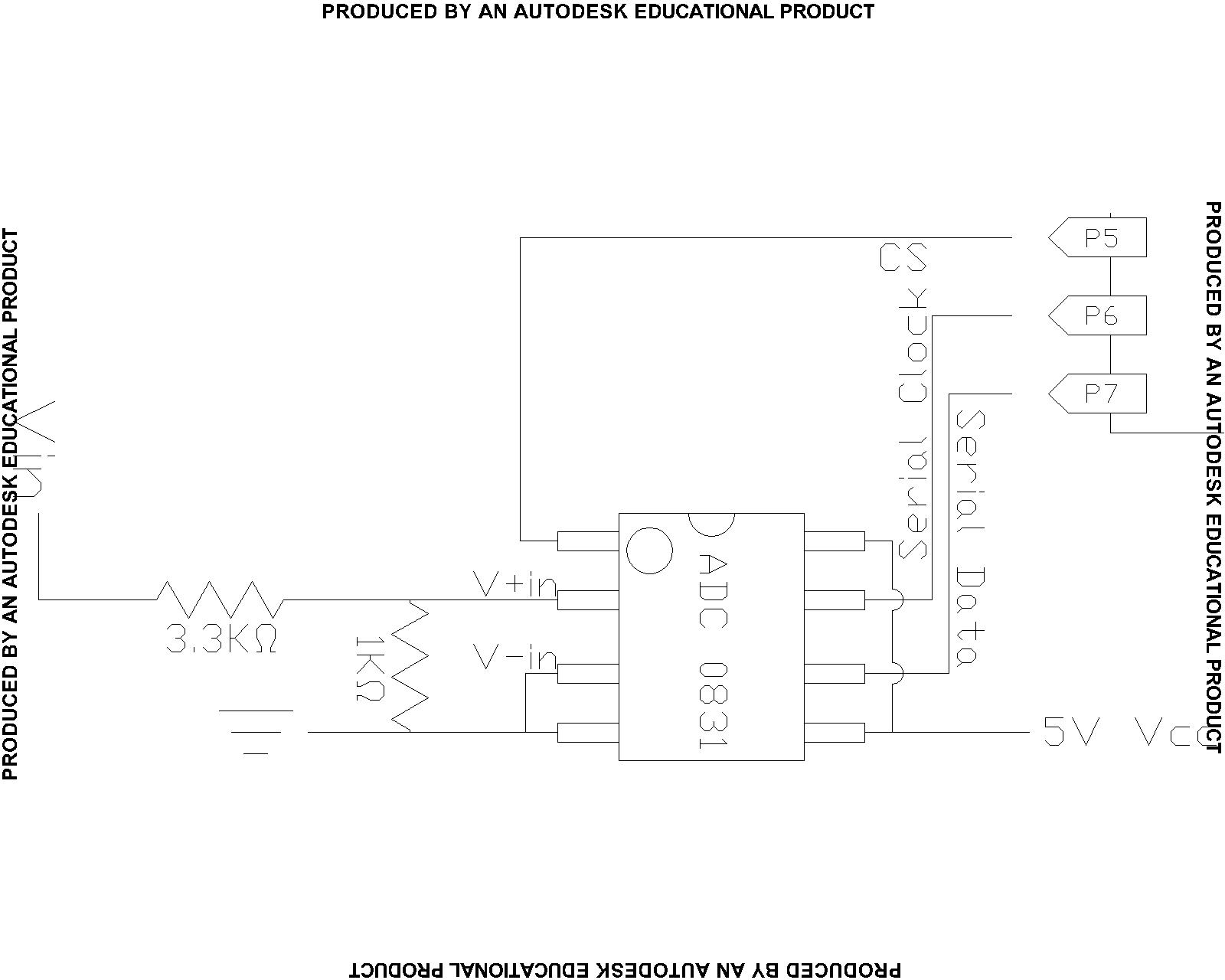
I am using a 5V Analog to Digital converter (ADC0831CCN). I am wanting to check voltages above 5V. The way I have done this is by placing a 1K-ohm resistor between V+in and V-in and a 3.3K-ohm resistor between the actual tested voltage and V+in (view attachment for diagram). This allows me to read up to 21.4V (or so - determined just by testing). I am wondering if there is a better way to test higher voltage and/or what is the math to determine exactly what the testable voltage is.
I understand that all I am doing is converting the 21.4V to 5V and anything between 0 and 21.4 is changed to something between 0 and 5. Any inputs or comments would be appreciated.
I understand that all I am doing is converting the 21.4V to 5V and anything between 0 and 21.4 is changed to something between 0 and 5. Any inputs or comments would be appreciated.
1600 x 1280 - 105K
Comments
For instance, a 10 ohm in series with 90 ohms will generate a 1volt signal across the 10 ohm resistor when the pair of them are energized by a 10 v source. So will a 10K ohm and 90K ohm resistor pair. Which one loads the circuit under test the most?
Sometimes, the loading doesn't matter ( say reading a battery voltage or power supply voltage), sometimes it will REALLY affect the reading of a sensor which has a high internal impedance.
Similarly, depending on your choice of a/d chip, it may load the voltage divider and affect your converted number.
Cheers,
▔▔▔▔▔▔▔▔▔▔▔▔▔▔▔▔▔▔▔▔▔▔▔▔
Tom Sisk
http://www.siskconsult.com
·
Post Edited (Bobb Fwed) : 6/16/2008 8:32:21 PM GMT
http://hyperphysics.phy-astr.gsu.edu/hbase/electric/voldiv.html
http://www.raltron.com/cust/tools/voltage_divider.asp
Steve
VADC = (R2 / (R1+R2)) Vto measure
As stamptrol·mentioned, you need to be carefull selecting the values of R1 and R2 so that the current drawn by the voltage divider does not significantly change the circuit being measured and does not feed too much power into the resistors.
So what do multimeter's do to allow for for inter-circuit testing? Really high resistance? like instead of 3.3K-ohm and 1K-ohm they would use 3.3M-ohm and 1M-ohm? There is still a little draw (4.884µA instead of 4884µA @ 21V), but I would still imagine it would mess up precise measurements.
Post Edited (Bobb Fwed) : 6/16/2008 9:54:14 PM GMT