

Digital potentiometer from a shift register and resistor ladder?
 MarkS
Posts: 342
MarkS
Posts: 342
I need a digital potentiometer for the contrast control for a LCD module. The module's data sheet calls for a pot between 10K and 20K. The problem is that the only digital pots I'm finding are in SMD packages, unless I want to order them in large quantities and wait weeks. I do not care to do either and I'd like to stick with through hole components for this project.
It came to mind that I could use a shift register with latched outputs and a resistor ladder to approximate a digital pot. This would be extremely cheap and easy to do, but would it work? This is what I have in mind...
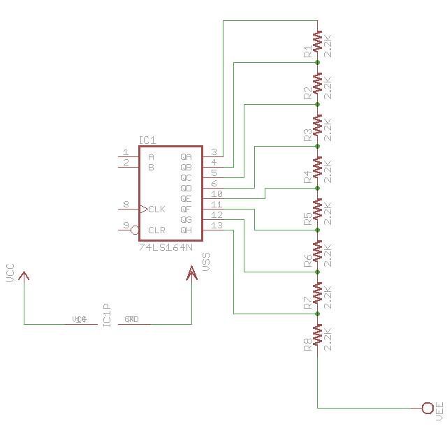
This would give a range of 2.2K Ohms to 17.6K Ohms.
Pay no attention to the shift register value as it was the first 8-bit shift register in the Eagle library. The contrast schematic can be seen on page 9 of the LCD module's technical specification data sheet.
I think this would work. Yes? No?
It came to mind that I could use a shift register with latched outputs and a resistor ladder to approximate a digital pot. This would be extremely cheap and easy to do, but would it work? This is what I have in mind...
This would give a range of 2.2K Ohms to 17.6K Ohms.
Pay no attention to the shift register value as it was the first 8-bit shift register in the Eagle library. The contrast schematic can be seen on page 9 of the LCD module's technical specification data sheet.
I think this would work. Yes? No?
Comments
Leon
▔▔▔▔▔▔▔▔▔▔▔▔▔▔▔▔▔▔▔▔▔▔▔▔
Amateur radio callsign: G1HSM
Suzuki SV1000S motorcycle
http://www.maxim-ic.com/quick_view2.cfm/qv_pk/2780
digi-key part number
http://search.digikey.com/scripts/DkSearch/dksus.dll?Detail?name=DS1804-010%2B-ND
▔▔▔▔▔▔▔▔▔▔▔▔▔▔▔▔▔▔▔▔▔▔▔▔
We all make mistakes when we are young………That’s why paste is edible!
Thanks!
http://en.wikipedia.org/wiki/Resistor_Ladder
▔▔▔▔▔▔▔▔▔▔▔▔▔▔▔▔▔▔▔▔▔▔▔▔
Chris Savage
Parallax Tech Support
▔▔▔▔▔▔▔▔▔▔▔▔▔▔▔▔▔▔▔▔▔▔▔▔
Chris Savage
Parallax Tech Support
Leon
▔▔▔▔▔▔▔▔▔▔▔▔▔▔▔▔▔▔▔▔▔▔▔▔
Amateur radio callsign: G1HSM
Suzuki SV1000S motorcycle
▔▔▔▔▔▔▔▔▔▔▔▔▔▔▔▔▔▔▔▔▔▔▔▔
We all make mistakes when we are young………That’s why paste is edible!
What I meant by software control is that the user will have a contrast setting in the menu. There will be a brightness setting as well, which will be done via PWM. I like the DS1804. It has just enough to get the job done.
▔▔▔▔▔▔▔▔▔▔▔▔▔▔▔▔▔▔▔▔▔▔▔▔
Chris Savage
Parallax Tech Support
That's a thought...
▔▔▔▔▔▔▔▔▔▔▔▔▔▔▔▔▔▔▔▔▔▔▔▔
Chris Savage
Parallax Tech Support
I was only looking for that as an option because I couldn't find a suitable digital potentiometer. However, I really like the DAC idea. That wouldn't have occurred to me. Thank you for that. That may be the most elegant solution.
After all, instead of being limited to available digital potentiometers, all sorts of resistance ranges can be employed.
Regardless of what you use, greater power levels may be managed through driver chips, like UNL2003 darlington array or transistors. The backlighting on an LCD can be a very power thirsty beast and might burn up a digital pot if directly connected, though I believe the control line is not high power..
For a long time now, I've felt intuitively there is a better way to manage latched incremental power increases than to have the microprocessor busy all the time with PWM. In this scheme to can send a level to the outputs, latch it, and have the microprocessor do some other task.
In some cases an R2R ladder is appropriate -- maybe most, but in other cases one might consider a voltage divider scheme.
And one doesn't have to use a shift register. A 4-bit to decimal chip might be a better fit if you can afford the I/O pins. In this way, you use the microprocessors I/O ports as your latches.
▔▔▔▔▔▔▔▔▔▔▔▔▔▔▔▔▔▔▔▔▔▔▔▔
PLEASE CONSIDER the following:
Do you want a quickly operational black box solution or the knowledge included therein?······
Post Edited (Kramer) : 6/19/2008 9:39:06 AM GMT
▔▔▔▔▔▔▔▔▔▔▔▔▔▔▔▔▔▔▔▔▔▔▔▔
Chris Savage
Parallax Tech Support
Could you do an example with the Prop instead? All of the examples seem to be for the BASIC Stamp and there are enough differences between the two to require separate examples.