

Mystery component help
 Pyrotom
Posts: 84
Pyrotom
Posts: 84
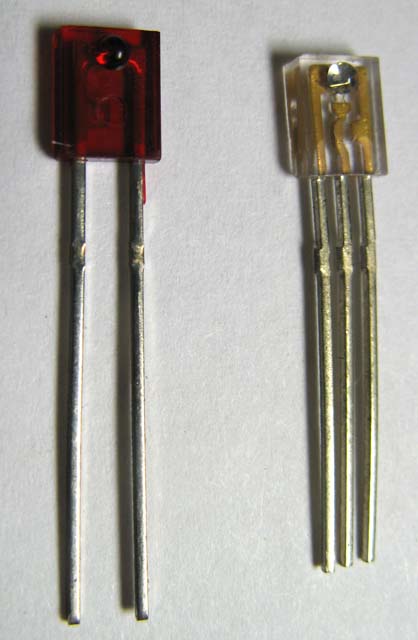
I'm working on a Prop based project which needs to sense flow of liquid in a pipe, so I was thrilled to find the "Unknown Flow Sensor" at All Electronics for a very reasonable price. The only problem I have is that "Unknown" bit.
I'm pretty good at programming, but not so hot on electronics, so I need a little help! I've attached a picture of the LED and what I assume is a phototransistor that are used in the flow sensor to watch a little paddle wheel turn. The LED is no problem, I can figure it out by trial and error. But how do I figure out what is what with the phototransistor (probably NPN, if my web research is correct), and can someone suggest a circuit to connect it to a Prop I/O pin so that I can read it? Thanks!!
Post Edited (Pyrotom) : 6/11/2008 7:43:25 PM GMT
418 x 640 - 48K
Comments
Leon
▔▔▔▔▔▔▔▔▔▔▔▔▔▔▔▔▔▔▔▔▔▔▔▔
Amateur radio callsign: G1HSM
Suzuki SV1000S motorcycle
None of the photo-transistors I've used have had a base lead, the light causes current to flow in the same way as current injected at the base. It is possible to use the base connection to adjust the sensitivity of the device, but I wouldn't bother with it.
Leon
▔▔▔▔▔▔▔▔▔▔▔▔▔▔▔▔▔▔▔▔▔▔▔▔
Amateur radio callsign: G1HSM
Suzuki SV1000S motorcycle
Post Edited (Leon) : 6/11/2008 9:41:23 PM GMT
-Phil