

Are there any results back from Parallax concerning PLL failures?
 Peter Jakacki
Posts: 10,193
Peter Jakacki
Posts: 10,193
I recently blew a couple of my chips while prototyping and they displayed the classic PLL failure problem, one even failed to start the crystal oscillator, otherwise everything else worked. Some time ago Parallax was looking into this failure perhaps to see if they needed to make some changes on Prop II I guess. I know that this is not really a failure of the chip design but a simple failure that is common to most overstressed chips.
What I would like to know is have Parallax discovered the mechanism behind the failures and is there anything we can do at the pcb level to make it less sensitive to such failures?
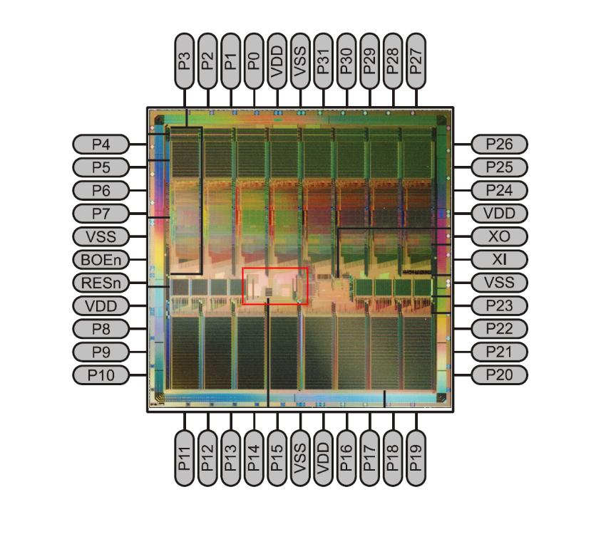
Just from my observations I have the lores pic of the prop die (is there a better one?) which I have traced through as best as I could to see if I could identify the areas. I noticed the concentric rings which I guess are VSS and VDD distribution buses but there are at least another 3 buses which may be I/O VDD and VSS. The oscillator and PLL seem like (logically) they are either near the reset circuit/band-gap ref (bottom left center).
*Peter*
P.S. I have attached an overlay of the die against the pinouts. It looks like the correct orientation.
Post Edited (Peter Jakacki) : 5/30/2008 11:32:13 AM GMT
What I would like to know is have Parallax discovered the mechanism behind the failures and is there anything we can do at the pcb level to make it less sensitive to such failures?
Just from my observations I have the lores pic of the prop die (is there a better one?) which I have traced through as best as I could to see if I could identify the areas. I noticed the concentric rings which I guess are VSS and VDD distribution buses but there are at least another 3 buses which may be I/O VDD and VSS. The oscillator and PLL seem like (logically) they are either near the reset circuit/band-gap ref (bottom left center).
*Peter*
P.S. I have attached an overlay of the die against the pinouts. It looks like the correct orientation.
Post Edited (Peter Jakacki) : 5/30/2008 11:32:13 AM GMT
850 x 750 - 76K
Comments
▔▔▔▔▔▔▔▔▔▔▔▔▔▔▔▔▔▔▔▔▔▔▔▔
Cheers,
Simon
www.norfolkhelicopterclub.co.uk
You'll always have as many take-offs as landings, the trick is to be sure you can take-off again ;-)
BTW: I type as I'm thinking, so please don't take any offense at my writing style
http://forums.parallax.com/showthread.php?p=719773
look particularity at the 7th post in this thread, Paul Baker gave some good tips and theory.
▔▔▔▔▔▔▔▔▔▔▔▔▔▔▔▔▔▔▔▔▔▔▔▔
Brian
uController.com - home of SpinStudio - the modular Development system for the Propeller
PropNIC - Add ethernet ability to your Propeller! PropJoy - Plug in a joystick and play some games!
SD card Adapter - mass storage for the masses Audio/Video adapter add composite video and sound to your Proto Board
Do you mean it is caused by terrorist attack to the PLL ?
▔▔▔▔▔▔▔▔▔▔▔▔▔▔▔▔▔▔▔▔▔▔▔▔
Regards.
Alberto.
No, that's not a terrorist attack, it is actually jumpy Israeli jet fighter pilots who react before they finished saying "PL..."
*Peter*
In case you missed it, here's the video http://www.youtube.com/watch?v=1uwOL4rB-go
*Peter*
Fred...Fred... Fred...
and ALL ships at sea.
This thread has it all... a great problem, great graphics, and unsurpassed humor. I just don't want to see it die.
You guys are engineers. I'm not. So, I am NOT going to try use the right technical terms, but I'll bet you a bottle of your favorite that there is a resonant condition that makes the PLL go pop...that's my intuition.
AND if my intuition is holding up, right before the PLL goes pop...if you could listen carefully enough you would hear the electrons saying... "oh...........oh....Oh.. OH.AHHHHHH (...) ouch."
What makes this reasonable to my brain is the fact that while electricity travels at close to the speed of light...electrons don't. It doesn't seem reasonable to me that the excess energy is being transmitted by "more" electrons... rather the electrons in the circuit must be picking up extra energy. Imagine a one dimensional cyclotron... in which (during each resonant interaction) the electrons gain energy. The frequency would be determined as an inverse function of the average axial distance between electrons, which should be a constant.
How would this translate to an experiment or a solution? That's engineering.
Rich
I can't stop to laugh, after I see the video... hahaha. It's great !!
I never saw they before.... very good show.
Anyway, although it's too funny, I'm waiting for somebody from Parallax, that answer to Peter.
I've too many propellers in the "streets", and I'm a bit afraid now, although I did never can to fried any PLL.
I would like to know too, exactly, ...why.
Really, I don't want to be a victim of Achmed.
▔▔▔▔▔▔▔▔▔▔▔▔▔▔▔▔▔▔▔▔▔▔▔▔
Regards.
Alberto.
▔▔▔▔▔▔▔▔▔▔▔▔▔▔▔▔▔▔▔▔▔▔▔▔
But back to the thread - Parallax answered (as Parts-Man said) in http://forums.parallax.com/showthread.php?p=719773
▔▔▔▔▔▔▔▔▔▔▔▔▔▔▔▔▔▔▔▔▔▔▔▔
Cheers,
Simon
www.norfolkhelicopterclub.co.uk
You'll always have as many take-offs as landings, the trick is to be sure you can take-off again ;-)
BTW: I type as I'm thinking, so please don't take any offense at my writing style
Yes and no. The reason I say no is that I am well aware of poor design practices or more correctly I am aware of good design practices and implement them in my designs. Of course I can still make mistakes but I am not aware of any of the problems that Paul mentioned. There were no inductive loads in my circuit but there is a 32V rail which goes to some drivers but of course the grounds are localized. The CPU is well away from the power drivers which have their own supply and ground planes and traces.
I was more interested in what does actually happen when the chip is stressed so as to fail in this manner. Knowing this helps to formulate a more complete and comprehensive plan for designing with the Propeller, being aware of the pitfalls and the failure mechanisms involved. Bars on windows for instance are a good protection - against break-ins - but not against mosquitoes. I've never had a design failed before so it must be a mosquito problem!
I'm quoting Paul's reply below for easy reference.
*Peter*
▔▔▔▔▔▔▔▔▔▔▔▔▔▔▔▔▔▔▔▔▔▔▔▔
Chip Gracey
Parallax, Inc.
I reviewed my pcb and found maybe two areas where I could have problems so I will make changes in this area for the production pcbs as these are only protos mostly to check the functionality. This design has an up-converter to +32V in the lower left hand corner which when overloaded (which happened) can draw some current. Part of the ground current would flow along the left through section A (attachment) and then through section B which means that it passes through the Propeller's ground pins. Of course this is not the primary current path but still it is a path. The solution is to isolate the ground at section A and although not as critical for different reasons the ground at section B.
This board really begs for more than 2 layers as it has to handle large currents so the final may indeed be four layer.
We all know and it's common sense that anything that is overstressed is going to give, so I don't blame the Prop Chip [noparse][[/noparse]pun] as anything to try and bolster-up in one area will just fail in another area, but where?. Better to know where the weak point is and then it's just plain science.
I have attached an image of the offending pcb for your information.
*Peter*
Edit, on topic. Found a discussion of stray voltages in a system in this pdf: http://focus.ti.com/lit/an/slva271a/slva271a.pdf·I guess TI was lucky because it was visible; they might might not have noticed it otherwise unless the stray voltage killed their chip. It's interesting that they mention that the effect is linked to 'time multiplexing'. The prop is all about multiplexing...
Post Edited (Fred Hawkins) : 6/5/2008 6:07:57 AM GMT
Do you have the 1uF ceramic capacitor, between pins 5 and 8, like the "demo board" have ?
I can't see it in your PCB, I always place it very close the pchip pins...
I can see only one, but in pins 17 and 18, I always use a 0.1uF there.
Maybe that could be a great reason for fails.
▔▔▔▔▔▔▔▔▔▔▔▔▔▔▔▔▔▔▔▔▔▔▔▔
Regards.
Alberto.
By the way, I really liked your video showing what causes PLL failure. That's·much more·dramatic imagery than·we glean from our·own tools. It's like a 'Fair and Balanced' approach to·failure analysis.
▔▔▔▔▔▔▔▔▔▔▔▔▔▔▔▔▔▔▔▔▔▔▔▔
Chip Gracey
Parallax, Inc.
Glad you liked my gif (finally used my animator from Ulead). The idea went like this: it would be cool to animate an explosion, then·an explosion·needs a terrorist, then remembered Achmed's "I·kill you" and couldn't stop laughing all afternoon. My better half suggests that Achmed's line may become an in-house Parallax meme much like in-home around here. Maybe not, though, there's always "seven".
·
-Thomas
@Thomas, thanks. (Now bigger, and with the prop plug terminal, please. Or maybe should I be greedy and go for the whole board?)
I am using Protel99SE and I configure it for transparent mode which makes it a lot easier to edit. I just adjust the colors a little so features are not obscured.
Almost any program creates a png though. Here's one way of doing though with freely available tools. Copy your screen to the clipboard and then import clipboard in Xnview, crop and save as filetype "png". Whereas GIF is a licensed filetype and is limited to 256 colors, PNG is non-lossy like GIF and ideal for handling graphics but offering far more compression than GIF. Both handle transparency but with PNG it's adjustable although IE has a bug handling it.
@Alberto, there is always at least one 0.1uF right next to the Prop or under it. The 1uf is part of the regulator module "SM7805+3" and as this "bulk capacitance" is not useful for transient response it does not have to be right next to the Prop. In fact the 1uf is mainly for the LDO regulator as it needs it to remain stable especially when there are sudden (relative to the regulator) extra load demands (i.e. Prop switches to XTAL+PLL16 mode from RCFAST etc). Having bulk capacitance in a circuit is always a good idea, expect it can be placed a little further away if necessary.
In saying all this there is no way that the omission or incorrect placement of a decoupling capacitor will cause the chip to fail. The chip may malfunction due to the supply glitches but it won't cause the silicon to fail. As Paul and Chip mentioned it usually is when you have excessive currents flowing through the ground pins of the chip, in my case it is remotely possible but I am more inclined to think that one of the I/O pins copped a hammering straight from 32 volts. So it's not a pcb layout problem, just one of those things that can happen when you have all those volts and amps lying about while prototyping.
I have included some other partial pcb layouts as examples. These are not perfect examples, just prototypes, but they give you some idea of the variations.
BTW, I'm happy to post specific layouts and schematics or even some complete ones for educational examples if that helps anyone. I might post them up and maybe they can be linked from the wiki?
*Peter*
Anyway for those interested here is the PCB layout we did.
I usually use this configuration without any damages of the chips, although some wires in the GND and VDD are not totally correct like (Paul suggest before and Chip said).
My LED screen has 17 propellers running many hours from the past October, never had fails. neither PLL's.
Like you, Peter said...maybe it is caused by (copped a hammering straight from 32Volt)... I don't know ...but with this PCB also all, works fine.
There are not ANY "inductors" in the circuit, and absolutely not excessive currents flowing through the ground pins of the chip.
This is one piece of the boards. (Image "b.png").
And I talk about the 1.0uF capacitor, NEAR the VDD and GND pins, because that:
(Images 1.jpg and 2.jpg)
▔▔▔▔▔▔▔▔▔▔▔▔▔▔▔▔▔▔▔▔▔▔▔▔
Regards.
Alberto.