

Propeller and RS232
 heathclf
Posts: 43
heathclf
Posts: 43
I'm trying to figure out how to grab a few sources of data with my propeller chip, combine them, and send them to my computer for logging. I'm pretty new to this, but I'm currently motivated, and I'd hate to get stuck this early on.
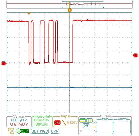
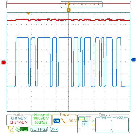
I just tried to transmit a '1' via a pin from my propeller my chip (using HelloFullDuplexSerial.spin), to my RS232 port, and read it in via Labview. It didn't work out so well. So then transmitted a '1' via my RS232 port (Labview controlled), and my chip both to an o-scope to compare the signals. Why is there such a big difference in the two signals (same baud), and how might I be able to transmit from a pin on the propeller chip to an RS232 pin?
Attached are pics of the two signals, if that helps at all.
556 x 545 - 49K
556 x 545 - 57K
Comments
The RS232 output that I posted earlier never saw the propeller chip. I just output a '1' from my RS232 so see what it thought a '1' looked like, so I could compare it to the signal it was getting from the chip (also a '1'), hoping they'd be identical, save for voltage levels. The fact that the two signals were different bothers me, and is the reason for this post. The pin being used is pin 30, which is the default tx pin of the HelloFullDuplexSerial.spin object that I was using.
I look forward to your response, and any ideas anyone might have...I'd really like to get this. Partially bc it'll be really useful, but mostly for the satisfaction.
Thanks,
Brad
Post Edited (heathclf) : 5/30/2008 4:40:53 AM GMT
2) The serial I/O (software) drivers for the Propeller are configurable for normal or inverted signalling with the default being normal. If you use inverted mode and use a protective resistor (like 10K) in series with the I/O pin, you could use the Propeller with the RS232 port for PC to Propeller. The reverse isn't quite true. The normal output logic levels of the Propeller are not high enough for an RS232 port. The actual logic high voltage of the Propeller is roughly 2.7V which is not high enough (+5V) for an RS232 port. The logic low voltage is near 0V (usually 0.3-0.6V) and is nowhere near low enough (-5V) for the RS232 port. You have to have some kind of level translating circuitry between the two.
The actual RS-232 high levels are less than 2.5V (typically 2V) and the low level not more than 0.8V according to the typical RS-232 chip's datasheets so it is quite possible that with a current limit resistor as you mentioned on the input and directly coupling the output to the PC that it can work. But of course the serial object has to be set to "inverted" logic as you also mentioned.
Although it is possible to connect to the PC this way it is not the ideal way of doing especially considering that there are so many RS-232 driver solutions out there. I also noticed that heathclf didn't use the same characters for transmitting and receiving as the PC transmit has 2 characters anyway.
*Peter*
P.S. That first timing diagram it's actually two characters ($31+$81). I haven't checked the second.
P.S. (again) that second timing from the PC is really weird. It appears to be five 7-bit characters $10,$10,$10,$19,$19. Go figure.
Post Edited (Peter Jakacki) : 5/30/2008 10:09:05 AM GMT
1 - After Peter took the time to look up the numbers, I realized I was sending some metadata in Labview as well, and not just a '1.'
2 - the propstick can write directly to the Serial, no level shifter needed. (though I didn't try the reverse, even through a resistor, as it's unrelated to what I'm currently doing.) I just needed to
With regards to Mike's statement about RS232 using inverted logic, I'm not sure that that's true. The attached pic is a propeller and an RS232 (correctly this time) both sending a '1' at 9600 baud. The logic seems normal to me.
Thanks for the input guys, small victories, amidst much frustration, make this stuff worth doing.
I got stuck thinking in terms of MAX232s and other RS232 and RS485 level shifters/converters that have inverted inputs and outputs for the logic circuitry.
In discussing maximum and minimum output voltages, I was assuming that there's a similar voltage drop in the output FETs as there is for other CMOS logic circuitry. That's where I got my numbers. I know these transistors have a higher drop with higher output currents and there would be some sag in the output voltage as circuit capacitances charge up, then the output voltage would move to a steady state nearer Vdd and Vss. Peter, if you've got numbers, please give them and I'll try to remember for next time.
You're the unanimous Propeller Guru and all-round helpful guy so this is a bit of a heads-up for you and anyone interested in this area of electronics.
There's an art to interpreting datasheets although it should be a science, it has to do with the way that the information is presented. For instance, sometimes people look at the "ABSOLUTE MAXIMUM RATINGS" and think they can run it at those levels but that's a bit like running your car at maximum revs, just how long do you think it might last?
Conversely we could look at the "min" and the "max" in the operating conditions and think that is what it is going to be but really they define the guaranteed worst case condition from the worst device in the worst environment. So the minimum high voltage out (Voh) from an I/O pin is spec'd at 2.85V for a rather heavy load of 10ma. So that means that the worst device in the worst environment (remember -55'C+125'C) will not be less than 2.85V with a VDD of 3.3V. As CMOS outputs are mostly resistive unlike bipolar devices we can even calculate what that worst case "ON" resistance is. Let's see, R=V/I where V=3.3V-2.85V= 0.45V and I = 10ma so that means the worst ON resistance will be 45 ohms.
So if we connect that pin to the RS-232 input on a PC under the worst conditions then the Voh will be calculated through the 45ohms and the input resistance of the RS-232 chip which is 3K under the worst conditions. This translates to a Voh of 3.25V and then we consider the worst case Vih (input high level) of the RS-232 chip is 2.4V so it's going to work even under the worst of the worst conditions with a good margin.
So you can see by looking at the worst case you can actually be optimistic about the design's performance, no ifs, no buts, no maybes.
Heathclf: If you look at that timing from the PIC it is already inverted as the transmit data to work directly into an RS-232 receiver. Normally the "logic level" transmit line idles high and only goes low when it's transmitting data so that when it is put through a proper RS-232 driver the output resembles the bottom trace with the transmit idling in the negative voltage state (around -6V). When I say logic level I mean what any UART on any CPU would output (and only outputs) before it hits the driver and gets inverted and turned into plus and minus voltages. Of course the Propeller is different in that it can emulate a normal UART or a custom UART or pretty much anything else with it's multiple cogs.
Small PICs normally do not have UARTS and bit-bash the serial data out at the expense of tying up the CPU resources while transmitting or receiving serial data (sorry buddy, I missed that emergency stop condition because I was busy sitting in delay loops while bit-bashing mundane updates).
*Peter*
propeller.wikispaces.com/Two-Resistor+Serial+Interface
Just to confirm; for a direct PC COM port to Propeller Pin interface, the line idles at 0V.
Post Edited (Agent420) : 6/4/2008 12:12:13 PM GMT
I like your circuit! Maybe I would drop the diode and call it an "All Resistor Serial Interface". Also, I think "330R" should be "330K", right?
Any chance of adding something for the DTR line to allow Programming of the Prop using just resistors?
Also, if that important signal were just a simple signal that could interrupt a process then it would just as easily be handled with some hardware. Many times that important signal is the result of a lot of sampling and processing. I've said it before about the Propeller and that is when it comes to temporally deterministic operation despite "critical" operational requirements, that the Propeller is capable of performing. All this!, in one simple tiny cheap chip that us regular guys can get to play with!
Hippy, your 2 resistor interface is overly complicated, you could skip the 330R
*Peter*
It was an electrical interface and was used by computers and terminals. The original protocol mostly used was synchronous (both ASCII and EBCDIC). Lsynchronous (UART) became the norm. If I remember correctly, the maximum distance was supposed to be 15m but I know I had it running 50m. The original specification was +-15V.
The PC changed a lot of this and the RS232 specifications have changed and the voltage has been lowered. I think RS232E called for a hysteresis of +-3V and operated at +-8V ???
Basically what we are doing with the propeller is usually only a few inches and certainly much less than 1m in length. We are not operating in noisy environments. So, if you are just interfacing to a PC serial port (or USB to RS232) you can get away with a resistor to limit the current, but a voltage divider of 2 resistors for the receivers would be better. Don't forget, if you are skipping the RS232 drivers on one end you will need to invert the signals (in the propeller software). If you are just driving the FT232 chip (or equivalent) then you are effectively skipping both inverters, so no change. If you connect the FT232 to 3V I/O you can skip the resistors, but it is still safer if you are using seperate power supplies.
A real UART scans at 16 times the clock (baud) rate and will report framing errors if the signal is out of spec. A soft UART (as in the FullDuplexSerial.spin object) only samples at the clock (baud) rate, which is done by waiting for the start bit, then delaying a half a bit before setting up the sampling at the clock rate (after skipping the start bit). I don't think it even checks for the stop bit. This is fine where the asynchronous interface is only being used locally with no noise and between processors.
I am using NMEA which is a different electrical interface (similar to RS232) used particularly on boats using TX, RX and GND. It uses +5V and GND but it should be isolated. So I am going to use an optoisolator to do the isolation. The standard·4800 baud will use simple optoisolation, but 38400 baud may require better (faster) optos. I will let you know when I have it running. I have Wind, Depth, GPS, Autopilot, Radio and AIS (later) to interface to the chartplotter software (Software On Board).
Hippy: You could do the DTR·reset interface with a diode and resistor. Unfortunately you will need to invert the output, since the default output will apply 0V to select reset. So just use the 2n2222 circuit (put a link in the base of collector line to disable.
Hope this helps.
Post Edited (Cluso99) : 6/4/2008 2:24:19 PM GMT
The 330R is really just protection against shorting the Prop output pin to 0V and against any PC serial port pull towards -12V. It could probably be left out, it could probably go higher.
The 1N4148 clamp to +3V3 is likely redundant with the Vdiode drop greater than that of the Prop's internal diode. I don't fit that, but do fit the blocking diode on input. Probably don't need that either but PICmicro's have ADC inputs affected otherwise, so force of habit.
I cannot take credit for the design.
I think programming interfaces are a separate case because of the inversion needed. Somewhere out in the forum I have a circuit which is designed to do programming using just TX/RX/0V and a 74HC00 powered from ProtoBoard 3V3. A serial 'break' is used to initiate reset. The big benefit is that opening and closing ports won't reset the Prop, allowing programming and run-time comms on P31/P30.
You're probably guessing by now that I'm not an electronics engineer - Transistors for me come in the form of logic gate ouputs
Gates are only transistors anyway (FETs are still transistors)