

A few electronics questions: Pullup resistors and transistors
 DiablodeMorte
Posts: 238
DiablodeMorte
Posts: 238
First off: this is kinda sorta related to a parallax product because eventually I plan to use a Propeller in my final board.
Ok, now for the meat of this post:
I'm just now getting into the world of PCB creation and my current project calls for a GPS module. The project calls for the final board to be VERY lightweight so I looked into creating my own GPS module. I found this(http://www.sparkfun.com/commerce/product_info.php?products_id=163) at Sparkfun. It weighs 6.5 grams and I can't image the antenna weighing much more than that so that's a 13g total weight. I think this is acceptable but I have some questions about wiring the PCB.
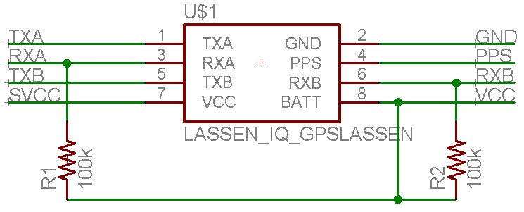
The Pullup Resistors
The manual for the GPS module calls for 2 pull-up resistors. I've never taken any formal electronics courses but I think I've wired those pins correctly. Here's the exerp from the manual:
1.) Table 1 shows the required connections for Rx pins of Lassen iQ when the pins are not used for communication:
Pin # Assignment Required Connections
3 Serial Port - RxA TSIP-IN High (VCC) *
6 Serial Port - RxB RTCM-IN High (VCC) *
From my interpretation that means that pins 3 and 6 need pull-up resistors. I've tried my best to wire the resistors but I'm not sure I've done it correctly. If anyone could look at the attached picture(Number 1) and maybe confirm or deny my wiring that would be nice.
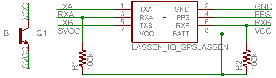
The transistors
I've never had much luck with transistors. I always seem to hit a wall-o-stupidity when ever I try to use one. What I want to do in this situation is use a transistor to turn on/off the GPS module. The GPS module seems to have two power supply pins(VCC and BATT). The VCC powers the chip, the BATT powers the onboard stuffs like RAM. I want to wire the module such that when the BI pin(on a seperate header) is driven high it would "activate" the transistor and allow current to flow to the VCC pin of the chip and thus turn it on(ie, consume more power). I want to do this so I can keep the GPS powered for things like ram but then be able to control when it is "on" and consumes the most power. Again, if anybody could look at the attached picture(Picture 2) and give me their take on my schematic.
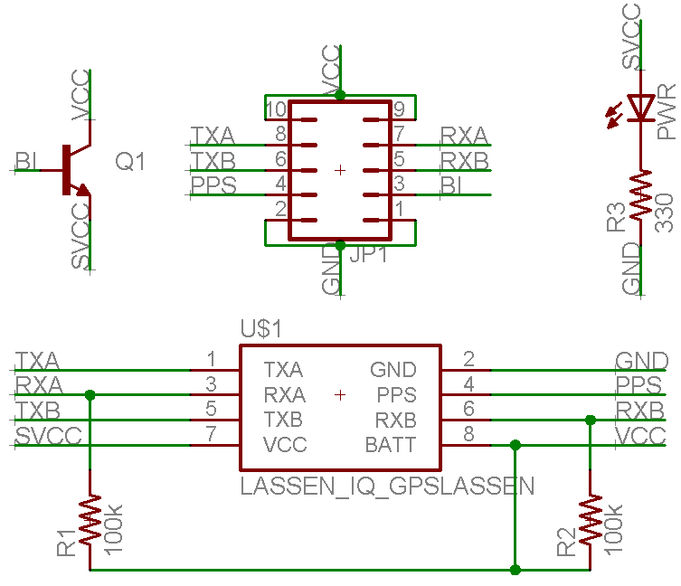
Finally, I've attached the whole schematic, if anybody could glance over it that would be very appreciated!
Regards
▔▔▔▔▔▔▔▔▔▔▔▔▔▔▔▔▔▔▔▔▔▔▔▔
Current Projects:
Robot Control Via Skype API - Dev Stage(50% Complete) - Total(25%)
Robot Localization Via Xbee's - Research Stage
IR Tracking with Propeller - Research Stage
Ok, now for the meat of this post:
I'm just now getting into the world of PCB creation and my current project calls for a GPS module. The project calls for the final board to be VERY lightweight so I looked into creating my own GPS module. I found this(http://www.sparkfun.com/commerce/product_info.php?products_id=163) at Sparkfun. It weighs 6.5 grams and I can't image the antenna weighing much more than that so that's a 13g total weight. I think this is acceptable but I have some questions about wiring the PCB.
The Pullup Resistors
The manual for the GPS module calls for 2 pull-up resistors. I've never taken any formal electronics courses but I think I've wired those pins correctly. Here's the exerp from the manual:
1.) Table 1 shows the required connections for Rx pins of Lassen iQ when the pins are not used for communication:
Pin # Assignment Required Connections
3 Serial Port - RxA TSIP-IN High (VCC) *
6 Serial Port - RxB RTCM-IN High (VCC) *
From my interpretation that means that pins 3 and 6 need pull-up resistors. I've tried my best to wire the resistors but I'm not sure I've done it correctly. If anyone could look at the attached picture(Number 1) and maybe confirm or deny my wiring that would be nice.
The transistors
I've never had much luck with transistors. I always seem to hit a wall-o-stupidity when ever I try to use one. What I want to do in this situation is use a transistor to turn on/off the GPS module. The GPS module seems to have two power supply pins(VCC and BATT). The VCC powers the chip, the BATT powers the onboard stuffs like RAM. I want to wire the module such that when the BI pin(on a seperate header) is driven high it would "activate" the transistor and allow current to flow to the VCC pin of the chip and thus turn it on(ie, consume more power). I want to do this so I can keep the GPS powered for things like ram but then be able to control when it is "on" and consumes the most power. Again, if anybody could look at the attached picture(Picture 2) and give me their take on my schematic.
Finally, I've attached the whole schematic, if anybody could glance over it that would be very appreciated!
Regards
▔▔▔▔▔▔▔▔▔▔▔▔▔▔▔▔▔▔▔▔▔▔▔▔
Current Projects:
Robot Control Via Skype API - Dev Stage(50% Complete) - Total(25%)
Robot Localization Via Xbee's - Research Stage
IR Tracking with Propeller - Research Stage
Comments
Thanks for the help Mr. Green!
-Regards
▔▔▔▔▔▔▔▔▔▔▔▔▔▔▔▔▔▔▔▔▔▔▔▔
Current Projects:
Robot Control Via Skype API - Dev Stage(50% Complete) - Total(25%)
Robot Localization Via Xbee's - Research Stage
IR Tracking with Propeller - Research Stage
Anybody have any other comments on the schematic?
-Regards
▔▔▔▔▔▔▔▔▔▔▔▔▔▔▔▔▔▔▔▔▔▔▔▔
Current Projects:
Robot Control Via Skype API - Dev Stage(50% Complete) - Total(25%)
Robot Localization Via Xbee's - Research Stage
IR Tracking with Propeller - Research Stage
one switches the high side, one switches the low side..
somethings are done easier/better using one or the other.
as to which is which.. its been soo long since electronics at votech.. so I dun think I can say.
·
Just wondering if any one has written any (propeller spin or pasm) code to use the Trimble TSIP GPS protocol ?... and how well did the Trimbol GPS unit work (sensitivity wise)
Cheers,
S
.. sorry completely off topic I know - this was the only reference to Trimble TSIP I could fine here.
▔▔▔▔▔▔▔▔▔▔▔▔▔▔▔▔▔▔▔▔▔▔▔▔
News Flash!... Energizer Bunny arrested and charged with battery.
Post Edited (Shane De Catania) : 10/30/2008 1:19:49 AM GMT
▔▔▔▔▔▔▔▔▔▔▔▔▔▔▔▔▔▔▔▔▔▔▔▔
Paul Baker
Propeller Applications Engineer
Parallax, Inc.
Post Edited (Paul Baker (Parallax)) : 10/31/2008 9:31:54 PM GMT
▔▔▔▔▔▔▔▔▔▔▔▔▔▔▔▔▔▔▔▔▔▔▔▔
Timothy D. Swieter, E.I.
www.brilldea.com·- Prop Blade, LED Painter, RGB LEDs, uOLED-IOC, eProto fo SunSPOT, BitScope
www.sxmicro.com - a blog·exploring the SX micro
www.tdswieter.com
One of the most overlooked reasons when using a single bi-polar PNP transistor is that if the voltage level that you are switching exceeds the voltage level you are driving the base of the transistor with by the bandgap voltage value (typically 0.6V).· If that happens, the transistor will never turn "off" because the difference in voltage across the B-E junction will always exceed the bandgap voltage.· One way to fix that situation is to use a second NPN transistor and a pull-up resistor forming a HIGH-side driver.
Another common reason is that if the base voltage of the PNP transistor can not be driven completely to the positive rail.· This may allow the transistor to turn on, but depending on the load demands placed on the PNP transistor, it may not completely saturate causing the transistor to operate in its linear mode, or hover right at the edge of its linear mode region.
Edit:·· Actually the second·statement above·I got backwards... If the PNP transistor can not be driven completely to the positive rail, the transistor will not be able to turn completely "off" and it will try to operate in it's linear mode.· Similar reasons·to the first statement above.
·
▔▔▔▔▔▔▔▔▔▔▔▔▔▔▔▔▔▔▔▔▔▔▔▔
Beau Schwabe
IC Layout Engineer
Parallax, Inc.
Post Edited (Beau Schwabe (Parallax)) : 11/7/2008 4:44:58 PM GMT
▔▔▔▔▔▔▔▔▔▔▔▔▔▔▔▔▔▔▔▔▔▔▔▔
Timothy D. Swieter, E.I.
www.brilldea.com·- Prop Blade, LED Painter, RGB LEDs, uOLED-IOC, eProto fo SunSPOT, BitScope
www.sxmicro.com - a blog·exploring the SX micro
www.tdswieter.com