

Use the reset button?
 Humanoido
Posts: 5,770
Humanoido
Posts: 5,770
Is it possible to have code see the reset button pressed
and go to another part of the code before the stamp resets?
I'm looking at the bs2px-24 with the attached schematic.
The code below won't work because reset is not on any of
the P0 throu P15 pins. It's on MCLR. I really need help with
this from one of the great stamp masters. (I'm developing
Penguin Pbasic code, do not want to add any keys, and
don't have other sensors to use because they are all being
used.)
humanoido
' {$STAMP BS2px}
' {$PBASIC 2.5}

Rst  PIN    1           ' note: needs MCLR pin, not 1
n    VAR   Word
n =  0

' when reset is pressed, pin MCLR goes low

DO
n = n +1
DEBUG DEC n
PAUSE 200
LOOP UNTIL (Rst = 0) ' wait until rst pressed
DEBUG "Rst was pressed"
STOP
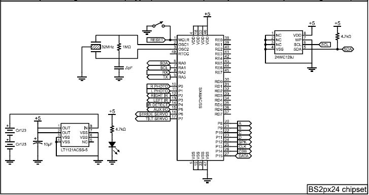
727 x 385 - 40K
Comments
-Phil
I don't think the Penguin as is comes from Parallax has a capacitor on the RESET input, so that would be a hack. Many of the Parallax products do have a capacitor on the ATN input.
The input pin might be the auxiliary input you have available on Penguin pin p5, or it might be possible to do some clever multiplexing with one of the other assigned pins.
▔▔▔▔▔▔▔▔▔▔▔▔▔▔▔▔▔▔▔▔▔▔▔▔
Tracy Allen
www.emesystems.com
thought put into each post and all the helpful information!
Phil, I like the code idea and found some information about
reset, but can you explain what's happening and offer some
comments?
Below is the test code. It works well and consistent. But one
question. How can the code be modified to "not report one
key press when first run?" I tried modifying it without luck.
humanoido
' {$STAMP BS2px} ' {$PBASIC 2.5} ' Use the reset button and count the number of times pressed ResetCount VAR Nib ' BASIC Stamp Syntax and Reference Manual 2.2 • www.parallax.com • Page 129 ' When the BASIC Stamp module is reset, all RAM variables including DIRS ' and OUTS are cleared to zero. This affects both main and auxiliary I/O ' pins. On the BS2p24, BS2PE, AND BS2PX, the auxiliary I/O pins from the ' interpreter chip are not connected to physical I/O pins on the BASIC ' Stamp module. While not connected to anything, these pins do have ' internal pull-up resistors activated, effectively connecting them to Vdd. ' After reset, reading the auxiliary I/O from a BS2p24, BS2pe24, OR BS2px24 ' will return all 1s. ' ---------------------- Main program ------------------------------- ' The following needs to be at the top of code: DEBUG "Start",CR READ 0, ResetCount WRITE 0, ResetCount + 1 MAX 15 PAUSE 500 WRITE 0, 0 ' ---------------------- Main Routine ------------------------------- 'This can come later... IF (ResetCount = 0) THEN DEBUG "1 button press",CR ' Execute code for one button press ELSEIF (ResetCount = 1) THEN DEBUG "2 button presses",CR ' Execute code for two button presses ELSEIF (ResetCount = 2) THEN DEBUG "3 button presses",CR ' Execute code for three button presses ELSEIF (ResetCount = 3) THEN DEBUG "4 button presses",CR ' Execute code for four button presses ELSEIF (ResetCount = 4) THEN DEBUG "5 button presses",CR ' Execute code for five button presses ELSEIF (ResetCount = 5) THEN DEBUG "6 button presses",CR ' Execute code for six button presses ENDIF STOP1. When reset, the reset count is read from EEPROM, incremented, then written back.
2. As long as resets keep occurring within 500ms of each other, this number keeps getting incremented until it reaches 15.
3. If more than 500ms transpires after the last reset, the count in EEPROM is set to zero for the next round of resets.
4. The last value read from memory is the reset count, minus 1.
-Phil
interesting, with the reset button showing any single reset as a single
keypress (button pressed or not) - As Mike Green pointed out, a
reset is just that. It's remarkable code, as through software there
are 15 functions that can be gained through pressing this one reset
switch. That solves my original challenge and I thank you very much
for your help. I have this working in new code and will post the entire
application when completed so everyone can benefit from it.
Tracy Allen, thank you for the hardware technique which is a very
good idea for some great Penguin Robot hacking. There's no capacitor
on Penguin's RST input line but there is one on BOE. Any idea why the
inclusion and exclusion? Attached is a comparison of the reset circuit
schematics of BOE and Penguin, side by side. For reference, the BOE
shown is rev. C.
humanoido