

stepper motor help
 realolman
Posts: 65
realolman
Posts: 65
I would like to operate a component of a machine that contains a stepper motor on the test bench, for the puposes of adjustment and repair. I feel sure the OEM would frown upon this activity, so I don't think I could get much help from them.
I have an Oriental brand bipolar stepper motor with 4.5 ohms per winding. It is connected to a Sanken A2918SW motor driver. If anyone is interested the documentation is at :
stepper motor documentation
There is not as much info on this model as others. I have disconnected the stepper driver board from the rest of the component, and am enabling and phasing it with a BASIC STAMP according to the truth table on the documentation. I think I have the sequence correct because I have tried all the combinations I can think of and this one seems to be the best.
The problem is it doesn't seem to have as much torque as it should.
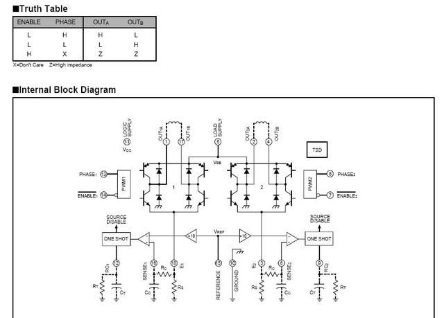
VBB > Vref = 39VDC, and I am using enable ,1 enable 2, and phase 1, and phase 2 . It seems to me from looking at this drawing that I should have something hooked to E1 and E2, but I don't ... should I have something hooked to E1 and E2...any suggestions on the resistor values?
The picture is kinda small E 1 and E2 are hooked to the bottoms of both sets of transistors... pins 18 and 3
thanks
I have an Oriental brand bipolar stepper motor with 4.5 ohms per winding. It is connected to a Sanken A2918SW motor driver. If anyone is interested the documentation is at :
stepper motor documentation
There is not as much info on this model as others. I have disconnected the stepper driver board from the rest of the component, and am enabling and phasing it with a BASIC STAMP according to the truth table on the documentation. I think I have the sequence correct because I have tried all the combinations I can think of and this one seems to be the best.
The problem is it doesn't seem to have as much torque as it should.
VBB > Vref = 39VDC, and I am using enable ,1 enable 2, and phase 1, and phase 2 . It seems to me from looking at this drawing that I should have something hooked to E1 and E2, but I don't ... should I have something hooked to E1 and E2...any suggestions on the resistor values?
The picture is kinda small E 1 and E2 are hooked to the bottoms of both sets of transistors... pins 18 and 3
thanks
Comments
Don't see how that could work, the H-bridges have·no (direct) path to Ground.·
I haven't read the datasheet in depth, but those Rs resistors are part of a current-sensing scheme.· I figure they should be very low values (maybe even "0" if you can go without any current-sensing, supposing it's "optional.")
·Do you think the driver needs the sense resistors to operate properly?
There really isn't as much info in the spec sheet as might be useful.
I'm not looking to operate this thing continuously, but only on the bench under my supervision to adjust things.
Post Edited (realolman) : 5/18/2008 3:22:08 PM GMT
·The VBB voltage is 39 vdc. I know the windings are 4.5 ohms.· The thing runs the way I have it hooked up, but it doesn't have much torque. I suspect it is finding a return through something not intended.
·It is hooked up partially to my stuff ( the basic stamp ) for input pulses, which seems to be working, and partially to it's own stuff.· The 39 VDC power, although it is supplied by me at the bench, goes through normal machine circutry.· There are a few lines disconnected, because I did not know their use ( different nomenclatures than used in the driver lit. ).· I will have to look more deeply into it tomorrow.
I was hoping someone who would know more about it than myself (like you ) would have some thoughts on it.
Hey you never know, you might run into the world's formost expert on the subject and the specific hardware.
The datasheet schematic and text description is crystal clear. That dotted line stuff isn't optional. It's required components outside the chip.
This is copied from the allegro 2918 datasheet:
PWM Current Control
The A2918SWH/V dual bridges are designed to drive both windings of a bipolar stepper motor. Output current is sensed and controlled independently in each bridge by an external sense resistor (Rs), an internal comparator, and an internal monostable multivibrator.
When the bridge is turned ON, current increases in the motor winding and it is sensed by Rs until the sense voltage (Vsense) reaches the level set at the comparator's input:
Itrip = Vref /10 Rs
The comparator then triggers the monostable which turns OFF the source driver of the bridge. The actual load current peak will be slightly higher than the trip point (especially for low-inductance loads) because of internal logic and switching delays. This delay (td) is 2 microseconds typically. After turn-off, the motor current decays, circulating through the ground clamp diode and sink transistor. The source driver's OFF time t-off , and therefore the magnitude of the current decrease, is determined by the monostable's external RC timing components, where t-off = Rt * Ct within the range of 20 k to 100 k and 200 pF to 500 pF.
When the source driver is re-enabled, the winding current (the sense voltage) again is allowed to rise to the comparator
Try .1 for the Rs (2-3 watt), 300ohm for the Rc, .1uF for the filter cap.
Determine the motors current rating max and adjust Itrip accordingly.
Say the motor is rated at 4 amps then:
Vref/10(.1Rs)
4/1
Set 4 volts to the ref as your current limit.
Try 50k on the Rt and 200-300pF for Ct.
Post Edited (Originator) : 5/19/2008 9:12:17 AM GMT
Whicker, I did a search for allegro 2918 and came up with a much better datasheet... apparently the one you have.
I do have control current, and the motor will turn.· I believe that the· missing resistor·is the problem, but my info showed nothing beyond the diagrams.· There was no text description.
·I searched for A2918SW and came up with very little, but a datasheet on a bunch of products (Sanken) of which this was one, but the info was very incomplete.· I only say that because I did make an effort to find info on this before I hooked anything up, or I posted here.
·I realize I am fooling around with several thousand dollars worth of stuff here.· It's a little stressful.· Sometimes you have to fly by the seat of your pants if you want to make any progress.· I tried to use every precaution I could , and so far·I have two power supplies, a laptop,· a basic stamp, and probably 15,000 bucks worth of machine parts hooked up, and while it didn't work correctly,· I don't think anything is·damaged either .... yet.··
·Thank you very much for posting.
I really appreciate all the help from everyone who replied. I think with your help and this new and improved datasheet, I will be able to do some good.
Thank you very much for your replies
Post Edited (realolman) : 5/19/2008 10:32:50 AM GMT