Sequential Taillights
Hi all,
This is my first post in Completed Projects.· I made a sequential taillight system for my 1965 Ford Mustang.· I’ve seen this type of taillights system in older Mercury Cougars,·and I really liked the way it looked.· The control units I’ve seen consisted of a motor that controlled relay type contact to operate the different bulbs.· I wanted a more modern setup, and so I decided to make one controlled by a BasicStamp1.· I used a BasicStamp1 because it had enough I/O pins, and was cheaper than the BasicStamp2.· I also used LED replacement bulbs, to lower the power requirements.
I programmed the Stamp to·operate the blinker from the inner most light, then the middle one, and then the outer most light.· After a slight pause, they all go out, and then it starts all over again.· It stops when the blinker is shut off.· When power comes into both right and left side at the same time, like when the break pedal is pushed, the break lights come on.· The power for the running lights/park lights run with the other wires, but is not affected by the Stamp.· The program has subroutines for NORMAL, BREAK, RIGHT &·LEFT.· The program is very basic, and works great.·
·
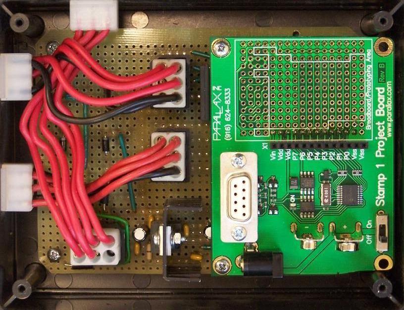
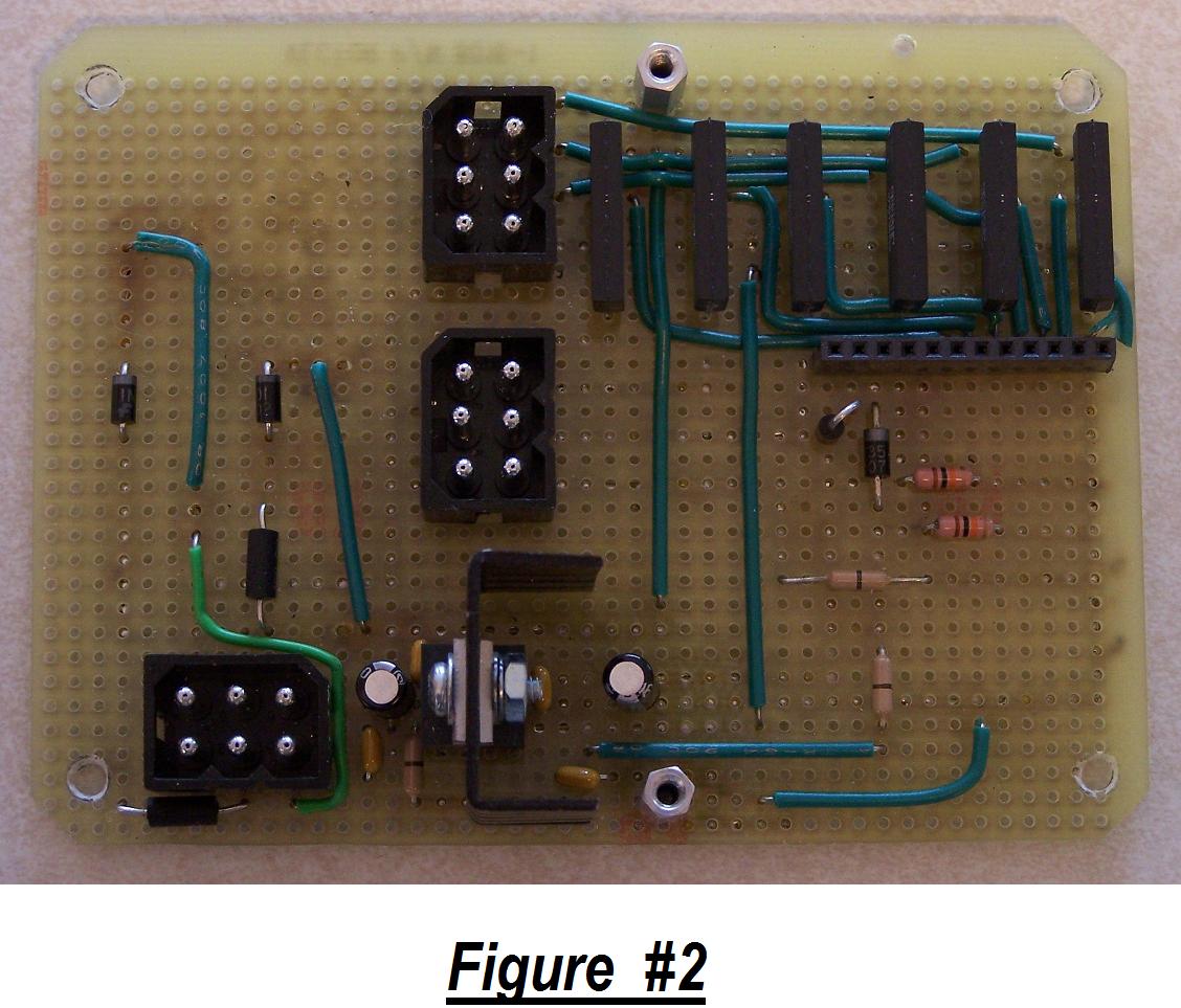
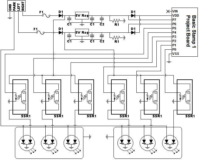
·I use 6 Solid State relays to control the 6 different bulbs.· I piggybacked the BasicStamp1 onto my board to make things a lot easier.· I used 2 voltage regulators at to bring each of the 2 input lines to 5 volts.··When 12 volts is applied to an input line, it steps it down to 5 volts, and that is used to power the·Stamp on, and provide the input signal for the program.· I·decided to do it this way to minimize how long the voltage regulators·are powered up, and how much heat they will have to·deal with.· So when the blinkers or breaks are not being used, the Stamp is not be powered, and the·voltage regulators are not heating up.
·
I used 470uf capacitors and 1uf capacitors across the regulators to handle the power fluctuations.··I used 10K ohm resistors as pull-down resistors, on each of the input pins.· I used diodes on each line to protect the Stamp from reverse voltage.· I also used diodes on each input pin, because powering the stamp and the pin at the same time, I had to prevent the power from bleeding from one pin to the next.··
··
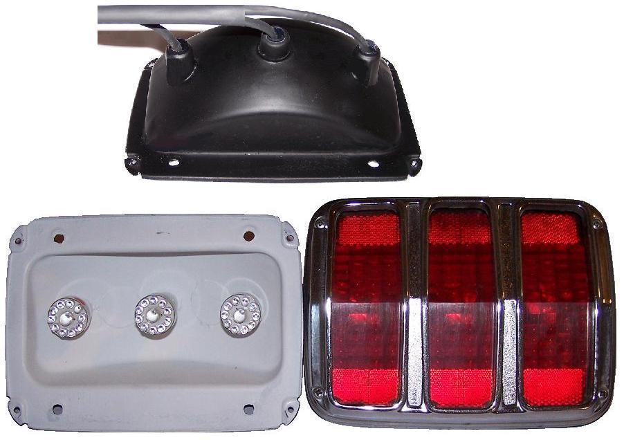
My next step was to design a taillight assembly that would have 3 bulbs for each side, because the Mustang taillight originally only used 1 bulb.· So I reworked the original housing, and added 2 more sockets, so it would now have 3 bulbs. ·I made a new wiring harness to connect the lights to the control unit, and included connectors to make the installation easier.
·
Solid State relays seemed to work better then Reed type Relays.· However, when I got this working, I wanted to see how it would look with the original incandescent type bulbs, and they did not light.· Turns out this caused the 3 relays on that side to burn out.· They were rated for 600mA, so I thought they could handle it.· I don't know if this will always happen, but it's what happened to me.· Once I put the LED bulbs back in and replaced the relays,·everything worked·again.·
I·also want to make a universal setup that can be used in any vehicle.· This would use regular 5mm LEDs instead of the bulbs, and only one LED will be lit at one time.· Then I would only need a relay to handle the heavier load when all LEDs are lit.· For the universal setup, I plan to use the BasicStamp 2, because I would have 8 more I/O pins for lighting more LEDs.· I was also checking out some LED driver ICs that may make the setup easier.· Using the BasicStamp 2 with more I/O pins could be used to activate a sub-routine for Emergency/Hazard flashers.· My mustang does not have the Emergency Flasher option, and I did not want to add it at this time.· I'm just glad to get a project done and working.
Thank you for a wonderful and informative forum.
▔▔▔▔▔▔▔▔▔▔▔▔▔▔▔▔▔▔▔▔▔▔▔▔
David
There are 10 types of people in this world,...
Those that understand binary numbers, and those that don't!!!


Comments
▔▔▔▔▔▔▔▔▔▔▔▔▔▔▔▔▔▔▔▔▔▔▔▔
Whit+
"We keep moving forward, opening new doors, and doing new things, because we're curious and curiosity keeps leading us down new paths." - Walt Disney
Now all I need to do is find the time to finish the car.
Talk to you later.
▔▔▔▔▔▔▔▔▔▔▔▔▔▔▔▔▔▔▔▔▔▔▔▔
David
There are 10 types of people in this world,...
Those that understand binary numbers, and those that don't!!!
You can get all the details in my July Nuts & Volts column.
That's a very neat little setup. I used the Basic Stamp 1 because my program and requirements were very simple. If I have to expand, I'll have to look to something else. I've never used the SX, but like a lot of Parallax items, the options get better and better.
▔▔▔▔▔▔▔▔▔▔▔▔▔▔▔▔▔▔▔▔▔▔▔▔
David
There are 10 types of people in this world,...
Those that understand binary numbers, and those that don't!!!